This page describes the Projector Plugin in Micro-Manager 2.0(gamma). For 1.4, see Projector-1.4.
The Projector plugin provides a single graphical user interface for controlling SLMs (spatial light modulators), such as DMDs (digital mirror devices), LCOS (liquid crystal on silicon) modulators or even digital computer projectors, and also for controlling steerable-mirror (e.g. galvo-based) phototargeting devices, including the Rapp UGA-40, the Andor MicroPoint, and the ASI scanner.
The Projector plugin’s interface shows three tabs: Point and Shoot, ROIs, and Setup. How to operate each tab is described in detail below.
Setup tab
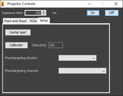
The Setup tab lets you test the phototargeting device and relate its coordinates to that of your camera (calibrate). You will need a thin sample that fluoresces when you illuminate with your photo-targeting light source. You also will need to focus at the same height as your real sample will be. We have had good luck with the plastics of certain multi-well plates, the plastic in between wells of some plates fluoresces nicely when illuminated with 405nm light. Other possibilities are highly concentrated dye solutions, or “highlight” markers (but note that these leave thicker layers, making it hard to know exactly where your device is focused.
If your device controls the light source itself, you will not need to set a Photo-targeting shutter. If you do have shutter that controls the photo-targeting light source, select it before you start. You may also want to select the channel optimized for photo-targeting at this point.
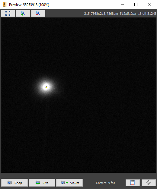
To start, press the “Center Spot” button. This should target your device to its center, which will hopefully be close to the center of your camera’s field of view. Use the “On” and “Off” buttons to turn the light on and off (in the case of a pulsed laser such as the MicroPoint, the On button will only turn the light on briefly). If the spot is not visible on a live image, the physical alignment of the camera and/or phototargeter may need to be adjusted.
Synchronization of the camera and the photo-targeting device is problematic (in part because all photo-targeting devices behave differently, some coordinate the light source themselves, outside of the control of Micro-Manager). To ensure that the illumination of the spot happens during a camera exposure (which we need for calibration), use the delay(ms) field. If the value is too short, you may not see any illuminated spots during calibration. The only downside of setting it too high is that calibration will take longer. Experiment (by starting Calibration) until you find a value that lets you (and the software) see spots during calibration
The Calibrate button starts an automated calibration procedure, where the phototargeter’s internal coordinates are mapped to the pixel coordinates to the camera’s pixel coordinates. This calibration allows the Projector plugin to convert mouse clicks or ROIs drawn on the live camera image into precisely directed phototargeting events.
The calibration procedure starts by illuminating a few spots near the center of the phototargeter range. This gives the Projector plugin an estimate of the orientation and location of the camera field of view relative to the phototargeter range. Then, points in a square lattice are illuminated one by one, and imaged on the camera. The Projector plugin uses the lattice measurements to compute a mapping of each pixel to phototargeter coordinates for future phototargeting. Mappings for each camera and phototargeting device are stored and will be remembered even after Micro-Manager is restarted. The relative orientation of the camera and phototargeting device does not matter; however they should be turned roughly square with each other (0, 90, 180, or 270 degrees) so that the square lattice isn’t cut off.
The calibration should be independent of the objective used, but will change when using different cameras. Currently there is no way to store different calibration mappings, e.g. for two different objectives.
| Setting | Description |
|---|---|
| Show center spot | Illuminate center of SLM or galvo device. |
| Calibrate | Creates calibration map of photo-targeting device range to the camera pixel position. |
| Delay(ms) | Use to synchronize photo-targeting exposure with camera exposure |
| Phototargeting Shutter | Shutter to be opened for photo-targeting. Not all photo-targeting devices need this to be set, for instance the Rapp UGA-40 controls the light source directly. |
| Phototargeting channel | Toggles to specified channel during phototargeting. You don’t need to set this unless some hardware needs to be moved during imaging, like a dichroic and/or a shutter. If you don’t see your channel listed, you must set the Core-ChannelGroup in the Property Browser to the Group containing this channel. |
Point and Shoot tab
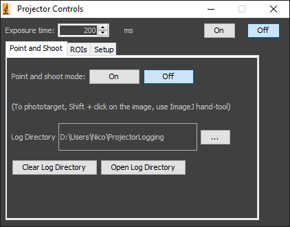
Point and Shoot lets you phototarget a small region instantaneously, by clicking on a live image of the specimen. Galvo-based devices fire a single shot, while SLM devices will turn on in a small region around the clicked pixel. The procedure is very simple:
- Under the Point and Shoot tab, set “Point and shoot mode” to “On.”
- Turn on live mode.
- Ensure that the ImageJ “Hand” tool is selected, hold down the Shift key (on the keyboard) and click anywhere in the live image window. You should immediately see a laser spot appear for a time at the clicked location. Duration of the Point and Shoot event can be set in the Exposure time field.
Point and Shoot events can be logged in a file. Set the location of the file in the dialog. The file will be named using the current date (yyymmdd) and contains timestamps and positions of the point and shoot click in image (pixel coordinates). Example:
2019-12-09 13:41:36.228 221 223
2019-12-09 13:41:42.559 347 368
2019-12-09 13:41:44.299 144 339
2019-12-09 13:41:45.831 199 143
ROIs tab
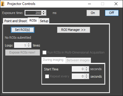
The Regions of Interest (ROIs) tab lets you specify regions on the image to be phototargeted. Phototargeting of an ROI can be carried out instantly, or programmed into a Multi-Dimensional Acquisition.
- Before running an ROI experiment, the calibration (described above under “Setup Tab”) must already have been carried out. Over time, the calibration may drift, so repeat calibration as needed. It’s also useful to try “Point and Shoot” first, to make sure the phototargeting hardware is working and the calibration is correct.
The procedure for illuminating a single ROI is as follows:
- Select one of the ROI tools on the ImageJ toolbar. Possible ROIs tools can include Rectangular, Oval, Polygon, Freehand, or Point. (Note that some devices, such as the MicroPoint and ASI scanner, currently only support Point targeting.)
- Press “Set ROI(s)”. The ROI will be uploaded to the phototargeting device.
- Choose a value of 1 or more for “Loop”. If Loop is greater than 1, then for every phototargeting event, the phototargeter will loop through the set of ROIs multiple times.
- Turn on Live mode (on the main Micro-Manager window).
- Press “Run Rois now!” The ROI should be illuminated (rastered in the case of a galvo-based device).
It’s also possible to run multiple ROIs:
- Click the ROI Manager button to display ImageJ’s ROI Manager.
- Draw an ROI, and press “Add.” The ROI will be included in the list. This is further detailed in Drawing Multiple ImageJ ROIs.
- Press “Set ROI(s)”, turn on Live mode, and then “Run Rois now!”
Pressing “Run ROIs now!” is a good way to phototarget the specimen during a Multi-Dimensional Acquisition. Just start the MDA, wait for the right moment, and then hit “Run Rois now!” to cause phototargeting to start, while acquisition continues simultaneously.
Alternatively, you can run ROIs at pre-determined time points in an acquisition sequence:
- Check Run ROIs in Multi-Dimensional Acquisition
- Enter a “Start Frame” index – that is, the first frame at which phototargeting should commence.
- If further phototargeting events are desired, check “Repeat every” and specify how many frames should elapse before the next phototargeting event should occur (after the first).
| Setting | Description |
|---|---|
| Set ROI(s) | Upload ROI(s) drawn on the selected image to the device. |
| ROI Manager | Add multiple ROIs to the image. |
| Loop | Number of times to target a group of ROIs. |
| Exposure time | Stops photo illumination after a certain interval. (Does not affect pulsed lasers or the Rapp Optoelectronic UGA-40.) |
| Run ROIs now! | Fires ROIs drawn on current image. |
| Run ROIs in Multi-Dimensional Acquisition | Fires phototargeting device at a pre-determined time during MDA. |
| Start Time | Timepoint in MDA to fire sequence. |
| Repeat every __ frames | Number of frames between successive phototargeting events in an MDA. Setup tab. |
Drawing Multiple ImageJ ROIs
If you are not as familiar with ImageJ ROIs and have been using ROIs in other software packages, some differences are:
- Only a single ROI can be drawn at a time. Drawing another ROI erases the current drawing, and so one must click the Add[t] button in the ROI Manager before drawing another ROI.
- To change a ROI that has already been added to the ROI Manager list:
- Select the ROI. The easiest way to select a ROI is clicking on the label as explained in the tips; alternatively, select the entry in the ROI Manager list.
- Reshape the ROI with the square white handles, or to change the type of ROI, draw the new ROI.
- Click Update.
Tips
- Delete all ROIs by double-clicking the ⌦ Delete button.
- Visually select a ROI by clicking the ROI’s center label number in the image. You will need to enable both the “Show All” and “Labels” checkboxs in the ROI Manager to do this.
- Move a ROI by dragging the ROI’s center label number in the image.
Also see the … ROI Manager section on the ImageJ User Guide.
FAQ
Can one stop the device firing at any time?
Unfortunately there is no emergency “off” button at the moment.
What happens when I target something outside the device range?
It ignores those clicks.