Introduction
In order to control a specific microscope, the Micro-Manager application needs to know what hardware is part of the microscope, load and initialize the appropriate drivers, define configuration presets, create labels for device positions, etc.. Typically, on startup the Micro-Manager application loads a configuration file containing commands configuring all aspects of the system. To start using Micro-Manager, you will first need to create a configuration file specific for your system
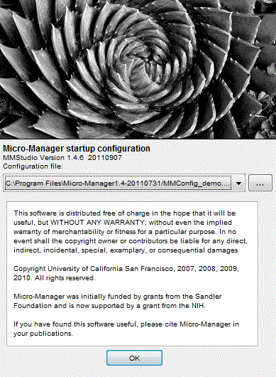
Figure 1. Startup screen: selection of the configuration file
Upon Micro-Manager startup an introductory splash screen pops-up
displaying the configuration file that is about to be loaded. By
default, Micro-Manager attempts to load the file used in the previous
session. You can either use that file, load another configuration file,
or start Micro-Manager with no configuration file by selecting “none”.
After pressing OK the initialization process starts and when it finishes
without errors, Micro-Manager is ready for use. Configuration files can
be also loaded at any time using the Tools | Load Hardware
Configuration command from the main menu. Each time you load a
configuration file, the current configuration is un-initialized (shut
down) and the new one is initialized. Re-loading a configuration file
has (almost) the same effect as restarting the application. You may also
switch and save any configuration files under the Tools menu.
The way to create a configuration file is by using the Configuration Wizard (Tools | Hardware Configuration Wizard), which will guide you, step-by-step, through the configuration process and generate a configuration file for you. The wizard will generate a text file that can be edited in a text editor. The syntax of this file is described below.
Hardware Configuration Wizard
The hardware configuration wizard guides you through the creation of a configuration file in 6 steps. Each step will display specific help in the right side of the wizard window. Before you begin, you should assemble as much information about your hardware as possible. For instance, you should know which serial ports of your computer are attached to what hardware. Preferably, you should test the functionality of the hardware with software provided by the vendor. Information and helpful advice about specific devices can be found in the Device Support page. When you get stuck, you can get support through the Micro-Manager mailing list. Remember, this is the most important part in getting Micro-Manager to be fully functional.
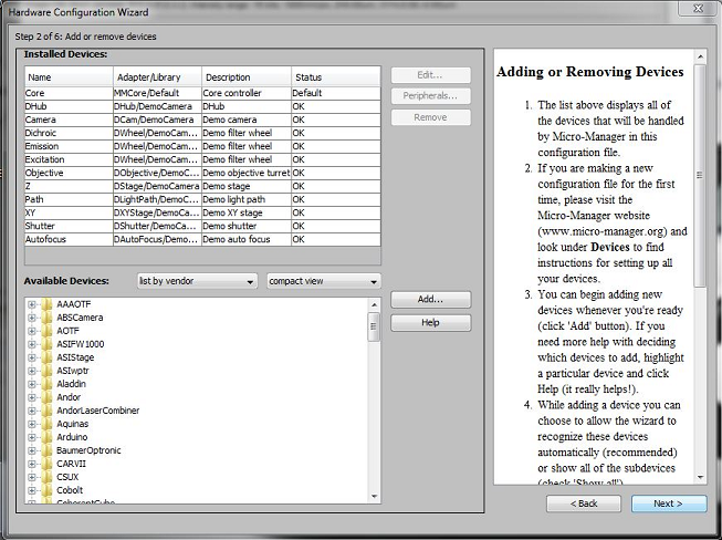
Figure 2. Step 2 of the hardware configuration wizard: selection of
devices.
If the device adapter you need shows up as “Unavailable”, you can check if
any of the dependecies for that device adapter are missing using one of the
Dependency Walker
alternatives (Windows only).
You can exit the wizard at any step by closing the wizard window. You
will be prompted to save the configuration file. Doing so (even when
something did not work) will be helpful in trouble shooting potential
issues. The most critical part of the wizard is in step 2. At this point
the hardware is being initialized, and errors/problems may manifest
themselves here. At the end of the wizard, save the file using the
‘.cfg’ extension.
Configuration Presets
Any property that Micro-Manager knows about can be changed using the Property Browser (Tools | Device/Property Browser). Changing properties using the Property Browser quickly becomes cumberson and impracticle. Micro-Manager therefore uses the concept of ‘Configuration Presets’ that let you quickly change a group of device properties. Configuring these Configuration Presets in a meaningful way is a very important part of configuring Micro-Manager. Configuration Presets also let you modify the User Interface of Micro-Manager to suit your needs.
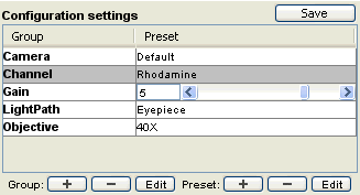
Figure 3. Example of Configuration Presets in the Main Micro-Manager
window
Before setting up Configuration Presets, you should familiarize yourself
with the Device/Property
Browser.
It is also worthwhile to experiment with the Configuration Presets in
the demo configuration.
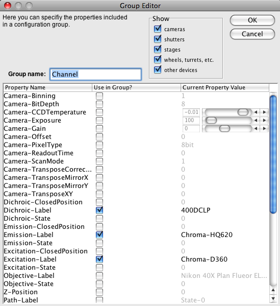
Figure 4. Initial Screen of the Preset Editor
To make a new configuration group (a new row in the table with
Configuration settings), press the Group ‘+’ button at the bottom
left of the Configuration Settings table. A Group Editor window will
appear that looks similar to the Device/Property Browser, but has a
third column called ‘Use in Group?’. Check the box in the ‘Use’ column
for any property that you want to be included in this configuration
group. For instance, you might want to make a group called ‘Channel’ in
which you ‘Use’ the emission and excitation filter wheels in your system
and also set the Core-Shutter (to switch between the fluorescent and
transmitted light shutter).
You will now be presented with a second window, (the Preset Editor), that will list only those properties you have chosen for your new group. Set the properties that you selected to their desired positions and name the Preset (for instance: ‘GFP’). Click ‘OK’, and you will have the first Configuration Prest in this group. To add Presets to the group, select the group (by clicking on the name of the group, ‘Channel’ in this example), and clicking the Preset ‘+’ button. The Preset Editor will appear again for each new preset. The ‘Configuration’ column in the user interface will now be a dropdown menu, selecting an item from this menu will change the state of your microscope.
When you select only a single property in the ‘Use’ column when making a new Configuration Preset Group, Micro-Manager will do some magic. For instance, when this property is displayed as a slider in the Device/Property Browser, a slider will appear in the main Micro-Manager window. If the property has a few values (like a filter wheel), all available values will appear in a dropdown list in the main window. This way you can quickly add control over a single device property, for instance the position of a filter wheel, to the main Micro-Manager window.
Once you are satisfied with your current presets you save them into the current configuration file (or a new one) using “Save” button next to ‘Configuration settings’. You can save the presets to the configuration file that you made previously. Next time you start up with that configuration file, your presets will be automatically loaded.
The ‘Edit’ and ‘-‘ (Delete) buttons allow you to change and remove Configuration Groups and Presets. If you add a property to a Group, then all existing Presets in that Group will now include the current value of the new Property.
Core Properties
In the Device/Property Browser you will find a list of properties of the Micro-Manager Core, such as core-camera, core-shutter etc. Micro-Manager can work with multiple cameras, shutters etc., however, commands will work only on the ‘active’ camera, shutter, etc. If your system has multiple shutters, such as a fluorescent shutter and a trans-illumination shutter you should set the ‘active’ shutter using the core-shutter property. In configuration groups, never set the state of a shutter directly, rather, rely on Micro-Manager’s Autoshutter functionality and use the core-shutter property to select the shutter that should be opened/closed. For instance, in GFP channel, set the core-shutter property to fluorescent shutter (and do not include the state of the fluorescent shutter) and in the DIC (or trans) channel set the core-shutter property to the trans-illumination shutter.
Startup Presets
There are a few configuration group/preset names with special meaning to Micro-Manager. If you make a configuration preset group called ‘System’, then you can define the groups ‘Startup’ and ‘Shutdown’. These configuration presets will be applied on startup and shutdown of Micro-Manager respectively.
Pixel Size Calibration
Pixel size calibrations are organized in a way similar to Configuration Preset Groups. You will define a group of properties that affect the pixel size, and when the current settings of the system ‘matches’ one of the Pixel Size Calibration ‘Presets’, Micro-Manager will apply that pixel size to the metadata of the images you take.
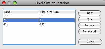
Figure 5. Pixel Size Calibration Editor
To set up Pixel Size Calibrations, start the Pixel Size Calibration editor (Tools | Pixel Size Calibration). Click the ‘New’ button.
![]()
The section at the bottom determines which properties will be part of the pixel size configurations. After defining the first pixel configuration only the selected properties will be shown. Check the boxes in the ‘Use’ column for those properties that affect the pixel size i.e objectives, auxiliary magnification (Optovar) etc. Do not check the camera ‘Binning’property (binning is automatically taken into account by Micro-Manager). Some other properties might not appear in the list since they are automatically taken into account (so called ‘Magnifier’ devices, these automatically tell Micro-Manager how they affect pixel size). Give this Pixel Size Calibration a name (the name is unimportant, it should be unique and might help you to remember the settings) and enter the pixel size. When you press ‘New’ again, only the previously selected properties will appear. Set these to the appropriate settings, give a label and the pixel size. The Pixel Size can also be edited inside the ‘Pixel Size calibration’ window.
The Affine Transform section determines the relationship between stage movement and the image on the camera. This will be affected by things like camera rotation and pixel size. It is very importanto for certain plugins, like Micro-Magellan. The affine transform is only useful when you have a motorized stage. The ‘Calculate’ button will calculate the affine transform based on the given pixel size. Use the ‘Measure’ button in the Affine Transform section of the Pixel Preset Editor to measure the affine transform and pixel size. Use a sample with strong contrast in the middle of the image. Follow the instructions in the Pixel Calibrator dialog.
![]()
Light Sheet settings are used to indicate the angle between the camera’s x and y axes and the axis of the z drive. This angle is dimensionless (i.e. the ratio of translation in x or y caused by a translation in z). This angle can be different for different z drives (if this is the case, please add the Core-Focus device to your pixel size configuration). Safe to ignore if you do not have a light sheet microscope.
Optimal Z step is used to guide microscope operators into using an appropriate Z step size. If you do not know what to set this to, try 3 x the pixel size. This value is displayed in the Multi-Dimensional Acquisition Dialog.
If a non-motorized device affects the pixel size calibration (for instance: your objective turret is non-motorized) you can add a device from the demo-adapter to represent this non-motorzied device and include this demo device in the pixel size calibration settings. When you now manually change the setting of the non-motorized device you should also change the setting of the demo device and Micro-Manager will select the correct pixel size calibration.
Do not forget to save the configurations after editing pizel size calibrations (you can use the ‘Save’ button next to Configuration Presets in the main window to this end). These settings are saved in the same file to describe the hardware and configuration presets (your ‘configuration’ file).
Configuration file syntax
A configuration is defined in a text file (with default extension
*.cfg) containing a list of simple commands to build the desired system
state: devices, labels, equipment, properties, and configurations. The
format is as follows:
* Each line consists of a number of string fields separated by “,”
(comma) characters. No extra spaces are allowed for formatting, i.e.
space characters will treated as parts of the field.
- Lines beginning with “#” are ignored (can be used for comments).
- Each line in the file will be parsed by the system and as a result a corresponding command will be immediately executed.
The first field in the line always specifies the command from the following set of values:
- Device – loads device
- Label – attaches a label to the specified device position
- Equipment – defines various equipment attributes used for image annotation
- Property – sets a specific device property
-
ConfigGroup – defines a single entry in the configuration group
Remaining fields in the line are used for specifying the corresponding command parameters. The number of parameters depends on the actual command used.
The following listing shows configuration file for the Demo setup.
<span><font face="Courier New">\# Generated by Configurator on Wed Jan
10 12:06:46 PST 2007

\# Reset
Property,Core,Initialize,0

\# Devices
Device,Camera,DemoCamera,DCam
Device,Dichroic,DemoCamera,DWheel
Device,Emission,DemoCamera,DWheel
Device,Excitation,DemoCamera,DWheel
Device,Objective,DemoCamera,DObjective
Device,Z,DemoCamera,DStage
Device,Path,DemoCamera,DLightPath
Device,XYStage,DemoCamera,DXYStage

\# Pre-init settings for devices

\# Pre-init settings for COM ports

\# Initialize
Property,Core,Initialize,1

\# Delays

\# Roles
Property,Core,Camera,Camera
Property,Core,Focus,Z
Property,Core,AutoShutter,1

\# Camera-synchronized devices

\# Labels
\# Dichroic
Label,Dichroic,9,State-9
Label,Dichroic,8,State-8
Label,Dichroic,7,State-7
Label,Dichroic,6,State-6
Label,Dichroic,5,State-5
Label,Dichroic,4,State-4
Label,Dichroic,3,State-3
Label,Dichroic,2,Q585LP
Label,Dichroic,1,Q505LP
Label,Dichroic,0,400DCLP
\# Emission
Label,Emission,9,State-9
Label,Emission,8,State-8
Label,Emission,7,State-7
Label,Emission,6,State-6
Label,Emission,5,State-5
Label,Emission,4,State-4
Label,Emission,3,Chroma-HQ700
Label,Emission,2,Chroma-HQ535
Label,Emission,1,Chroma-D460
Label,Emission,0,Chroma-HQ620
\# Excitation
Label,Excitation,9,State-9
Label,Excitation,8,State-8
Label,Excitation,7,State-7
Label,Excitation,6,State-6
Label,Excitation,5,State-5
Label,Excitation,4,State-4
Label,Excitation,3,Chroma-HQ620
Label,Excitation,2,Chroma-HQ570
Label,Excitation,1,Chroma-HQ480
Label,Excitation,0,Chroma-D360
\# Objective
Label,Objective,5,Objective-5
Label,Objective,4,Objective-4
Label,Objective,3,Nikon 20X Plan Fluor ELWD
Label,Objective,2,Objective-2
Label,Objective,1,Nikon 10X S Fluor
Label,Objective,0,Nikon 40X Plan Flueor ELWD

\# Configuration presets
\# Group: Camera
\# Preset: MedRes
ConfigGroup,Camera,MedRes,Camera,Binning,2
ConfigGroup,Camera,MedRes,Camera,PixelType,8bit

\# Preset: Default
ConfigGroup,Camera,Default,Camera,Binning,1
ConfigGroup,Camera,Default,Camera,PixelType,8bit

\# Preset: LowRes
ConfigGroup,Camera,LowRes,Camera,Binning,4
ConfigGroup,Camera,LowRes,Camera,PixelType,8bit

\# Preset: HiRes
ConfigGroup,Camera,HiRes,Camera,Binning,1
ConfigGroup,Camera,HiRes,Camera,PixelType,16bit


\# Group: Objective
\# Preset: 20X
ConfigGroup,Objective,20X,Objective,State,3

\# Preset: 40X
ConfigGroup,Objective,40X,Objective,State,0

\# Preset: 10X
ConfigGroup,Objective,10X,Objective,State,1


\# Group: Channel
\# Preset: FITC
ConfigGroup,Channel,FITC,Dichroic,Label,Q505LP
ConfigGroup,Channel,FITC,Emission,Label,Chroma-HQ535
ConfigGroup,Channel,FITC,Excitation,Label,Chroma-HQ480

\# Preset: Rhodamine
ConfigGroup,Channel,Rhodamine,Dichroic,Label,Q585LP
ConfigGroup,Channel,Rhodamine,Emission,Label,Chroma-HQ700
ConfigGroup,Channel,Rhodamine,Excitation,Label,Chroma-HQ570

\# Preset: DAPI
ConfigGroup,Channel,DAPI,Dichroic,Label,400DCLP
ConfigGroup,Channel,DAPI,Emission,Label,Chroma-HQ620
ConfigGroup,Channel,DAPI,Excitation,Label,Chroma-D360

\# Preset: Cy5
ConfigGroup,Channel,Cy5,Dichroic,Label,400DCLP
ConfigGroup,Channel,Cy5,Emission,Label,Chroma-HQ700
ConfigGroup,Channel,Cy5,Excitation,Label,Chroma-HQ570


\# Group: System
\# Preset: Startup
ConfigGroup,System,Startup,Camera,CCDTemperature,-85.26
ConfigGroup,System,Startup,Camera,Gain,3

\# Preset: Shutdown
ConfigGroup,System,Shutdown,Camera,CCDTemperature,0.00
ConfigGroup,System,Shutdown,Camera,Gain,0


\# Group: LightPath
\# Preset: Camera-left
ConfigGroup,LightPath,Camera-left,Path,State,1

\# Preset: Eyepiece
ConfigGroup,LightPath,Eyepiece,Path,State,0

\# Preset: Camera-right
ConfigGroup,LightPath,Camera-right,Path,State,2


\# PixelSize settings
\# Resolution preset: 20x
ConfigPixelSize,20x,Objective,Label,Nikon 20X Plan Fluor ELWD
PixelSize\_um,20x,0.5

\# Resolution preset: 40x
ConfigPixelSize,40x,Objective,Label,Nikon 40X Plan Flueor ELWD
PixelSize\_um,40x,0.25

\# Resolution preset: 10x
ConfigPixelSize,10x,Objective,Label,Nikon 10X S Fluor
PixelSize\_um,10x,1.0

</font>
</div>
Memory Settings
It is often necessary to adjust memory settings in order to optimize Micro-Manager performance and prevent errors. Different parts of Micro-Manager use different types of memory that can be individually tuned.
The ImageJ memory limit (ImageJ | Edit | Options | Memory & Threads…), and the sequence buffer size (Tools | Options) can be changed. These each need to be large enough for what they are used for, but small enough to leave RAM for the other, and for the Operating System.
The sequence buffer is used to hold freshly acquired images until the Micro-Manager application is ready to process (display, save, etc.) them. It helps absorb occasional glitches that slow down software processing, so that the camera can acquire images at its set rate. The sequence buffer is not used for Snap acquisitions or those Multi-Dimensional Acquisitions where there is plenty of time between frames.
The ImageJ memory limit (actually the maximum amount of memory that can be used by the Java Virtual Machine running ImageJ/Micro-Manager) determines the amount of RAM that can be used for general application memory. To complicate matters, some versions of Micro-Manager store images outside of this JVM memory (1.4 since 2013, and 2.0 until April 2020), whereas others (pre-2013 and 2.0 since April 2020) store images inside the ImageJ memory limit. If you are unsure which one you use, open the ImageJ memory monitor tool (ImageJ | Plugins | Utilities | Monitor Memory…), run an acquisition that stores a significant number of images in RAM, and note if the memory usage goes up accordingly (occasionally pressing the ImageJ status bar to invoke the Java memory garbage collector). If memory usage stays low, your version of MM stores images outside of the JVM memory.
Here are some guidelines for adjusting memory settings:
- If Micro-Manager stores images outside of the JVM, you do not need to set the ImageJ memory setting very large, unless you experience “out of memory” errors when processing images using ImageJ and ImageJ plugins. For the 64-bit version, 1-4 GB is recommended (but leave several GB of your total RAM for other purposes). For the 32-bit version, it is important not to set the ImageJ memory too large. 400-800 MB is usually a good range, and you should not exceed 1.2 GB (a little larger is okay on OS X).
- If Micro-Manager stores images inside the JVM (2.0 since April 2020), set the ImageJ memory limit as high as possible, but make sure the total amount of memory set for the circular buffer plus ImageJ does not exceed ~80-90% of the total memory in your computer.
- For the sequence buffer size setting, try first setting the buffer to 20-100 times the size of a single image from your camera. You may get “sequence buffer overflow” (also known as “circular buffer overflow”) errors during acquisitions, especially at high frame rates. If so, try increasing the sequence buffer size (for fast streaming of large images, much larger settings can sometimes be useful). You can also use the Sequence Buffer Monitor plugin (Plugins | Developer Tools) to see how much of the sequence buffer is actually used during a Multi-Dimensional Acquisition.
If you have another installation of ImageJ on your computer, keep in mind that Micro-Manager uses its own copy of ImageJ and that you need to set memory options on both.
Finally, note that the sequence buffer size setting is saved per user profile, while the ImageJ memory setting is saved per copy of ImageJ.
Troubleshooting
Micromanager GUI (MMStudio) handles other non-hardware settings through Java preferences API (java.util.prefs), so they’re persistent even after uninstall. In some cases (e.g. after using development version or upgrade) old properties can cause GUI misbehaviour (e.g. inability to save changed histogram range).
Windows user can find preferences in HKEY_CURRENT_USER\Software\JavaSoft\Prefs\Org\micromanager registry branch and remove manually. New properties will be created automatically. Hardware configuration remains unchanged.
Created on July 31, 2006 by Nenad Amodaj
Revised on January 31, 2007
Revised on August 21, 2008 by Nico Stuurman
Revised on May 16, 2012 by Ziah Dean
Revised on December 3, 2014, by Mark Tsuchida
Extended on October 5, 2015 by Eugene Dvoretsky
