This document provides an extensive guide to using µManager, and is recommended reading for new users.
Introduction
Modern microscopes have many computer-controlled components that need to work in harmony for accurate data to be collected. Shutters and light sources must be opened and closed with precise timing, synchronized with the camera that takes the image; filter wheels must be positioned to allow only the desired wavelengths of light; XY and Z stages must precisely position the sample. Performing even simple data acquisitions requires many precise steps to be carried out.
µManager is a program for performing these complicated data acquisitions. It handles all of the hardware control and synchronization, while presenting a simplified yet powerful interface that allows the user to easily set up the data acquisitions they want to use.
While this interface is all that the vast majority of users will ever need to use, the µManager developers know that optical microscopy is a continually-developing field, and scientists are continually experimenting with new techniques. For that reason, µManager provides its advanced users with direct hardware control, allowing them to implement customized behaviors while still leveraging the program’s convenient features for more conventional imaging. And if even that isn’t enough, µManager (unlike all other microscope control programs in common use) is open-source, so scientists always have the freedom to implement exactly the routines and techniques that they need to perform their experiments.
Finally, µManager has strong integration with ImageJ and with MatLab, allowing users to leverage these programs to perform their data analysis. In conjunction with ImageJ, µManager makes a powerful, flexible, and open-source microscopy “stack” with unprecedented levels of user control.
Installation
There are separate installation procedures for each of µManager’s three supported systems. You can download appropriate installers from Downloads page. In addition to the system-specific installation rules below, you may need to install drivers for your specific hardware. See the Device Support page for more information.
All installations include a built-in copy of ImageJ and automatic support for common hardware that does not require special drivers. When you launch µManager, it will automatically run ImageJ as well from its built-in copy. This version of ImageJ is separate from any version you may have installed independently. If you have customized your ImageJ installation (for example with extra plugins or macros), you can perform the same customizations to µManager by copying files from ImageJ to µManager.
While there are no specific minimum requirements for running µManager, we recommend a 64-bit system with at least a 1.7GHz processor. More RAM is often helpful for running high-speed acquisitions, and if you want to run extremely rapid acquisitions (upwards of 1GB/second of incoming data) then you should read High Speed Acquisition in Micro-Manager.
Installation on Windows
Run the installation .exe file (e.g. “MMSetup_64bit_xxx.exe”, where “xxx” is the version number). The software will be installed in your Program Files directory (typically at C:\Program Files).
Installation on MacOS X
Open the .dmg file you downloaded, by double-clicking on it. This will bring up a window that contains the µManager program folder. Copy this folder into your Applications directory to install it. For trial purposes you can also run it directly by simply double-clicking on it.
To deal with newer MacOS security features, you may need to first right click on ImageJ and select “Open” and then press the “Open” button on the window that appears. Also to deal with “randomization” do the following: Within the Micro-Manger folder in Applications, hold command and drag ImageJ onto the desktop. Then hold command and drag it back in. Then try running again. After these steps, Micro-Manager should start normally.
Installation on Linux
Please see Linux installation from source (Ubuntu).
Memory Settings
It is often necessary to adjust memory settings in order to optimize Micro-Manager performance and prevent errors. See the Configuration Guide for guidelines.
Getting Started
Intro Dialog
When you launch the program, you’ll be presented with a splash screen:
TODO insert new splash screen here!
This dialog has three important features:
Hardware Configuration Files
The “Configuration file” dropdown menu allows you to select a file that tells µManager how to communicate with the microscope hardware you have installed. If you’ve never run µManager before, then you won’t have one of these yet. For now, use the “MMConfig_demo.cfg” option, which contains a full suite of simulated hardware (all screenshots in this guide will be using this demo config). We’ll set up a proper configuration file later. Or alternately, select the “(none)” option to run µManager without any hardware.
User Profiles
µManager contains a user profile system, which is used to remember things like window positions, acquisition settings, recently-accessed files, and more. The “User profile” dropdown menu allows you to select which profile to use, and to create or delete existing profiles. User profiles are primarily useful if you have multiple people sharing the same operating system account; if each user has a separate OS account, then you can simply use the “Default profile” option for each person.
License Information
µManager includes contributions from a large number of people and organizations, and relies on many open-source libraries that each have their own licenses. The “License Info” button takes you to a dialog that lists all of the contributors and licenses that went into making µManager possible.
The µManager Main Window
Main Window
The main window in µManager provides access to many important capabilities.
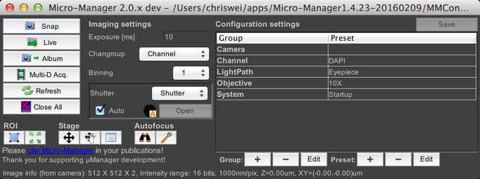
There’s a lot here, so we’re going to break it out into separate sections that we’ll tackle one at a time.
One quick note before we get started: on OSX, the menu bar at the top of the screen changes depending on which window has focus. If you want to access µManager’s menus, then the µManager main window must have focus.
Snapping Images and Live Mode
In the upper-left corner are the Snap and Live buttons. You can use these to acquire images using your current camera and illumination settings.

This will bring up an image window:
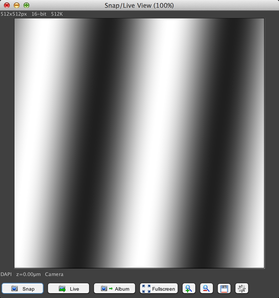
The test pattern displayed in this window was generated by the simulated camera that the MMConfig_demo.cfg hardware configuration file specified.
See Image Windows for more information.
The first new image window in each session also creates a new Inspector window:
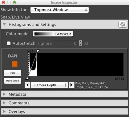
These windows allow you to adjust the contrast of your image display, provide access to image metadata, and more. See Inspector Windows for more information.
Using the Album

Clicking on the “Album” button will snap a new image and add it to the “album”, which is a simple collection of sequential images.
Acquiring Multi-Dimensional Datasets

The “Multi-D Acq” button brings up the Multi-Dimensional Acquisition dialog:
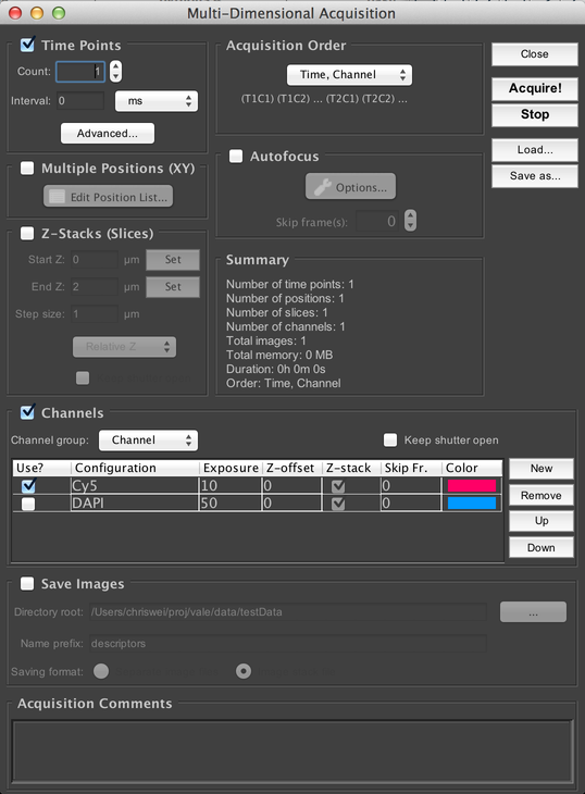
This allows you to set up complex image acquisitions: timeseries, Z-stacks, multi-channel, multi-stage-position, and combinations of those axes. See Multi-Dimensional Acquisition for more information.
Refreshing the UI

It is possible for the GUI to get out of sync with the current state of the microscope hardware (for example, if you manually move a computerized component, or if you use a joystick to move the stage). Clicking on the “Refresh” button will cause the GUI to update itself to accurately reflect the current state of the hardware.
Close All Image Windows

You may sometimes find yourself with an excess of image windows that contain throwaway data. This button allows you to close all currently-open image windows. It will prompt you for whether you want to get a save prompt for each window containing unsaved data, or if you would rather force all of them closed without further prompts.
Imaging Settings
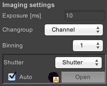
These settings allow you to control how images are acquired.
- Exposure: sets the exposure time for images. “Exposure time” in µManager always refers to the camera exposure time, not the sample exposure time.
- Changroup: set the config group that is used to control the channel
- Binning: set the bin mode for the camera, which allows you to combine multiple physical pixels together (for example, in 2x2 binning, 4 physical pixels are combined into a single image pixel).
- Shutter: set the hardware device that will be used for shuttering when images are acquired. If you have multiple different light paths (e.g. LED vs. laser vs. brightfield) then you can use this to switch between them.
- Auto/manual shutter controls: normally, µManager is in auto-shutter mode, where the shutter is opened automatically when images are acquired, and closed otherwise. By unchecking the “Auto” checkbox, you can switch to manual shutter mode, in which you can open or close the shutter by either clicking on the “Open/Close” button or on the shutter state indicator. This can be useful, for example, for illuminating your sample while looking through the eyepiece.
Configuration Groups
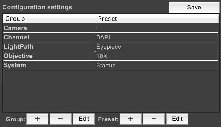
This section of the main window allows you to create and manipulate “config groups”, which are collections of related hardware settings. See Config Groups for more information.
Miscellaneous Settings

These buttons provide various miscellaneous features.
- ROI: allows you to set a “Region of Interest” on the camera, so that only a portion of the camera’s field of view will be used for imaging. On many cameras, this will speed up your maximum framerate. Use ImageJ’s rectangular selection tool on the Snap/Live view to draw the ROI you want to image, and then click on the left button to set the ROI; snap a new image to see the ROI in action. Click on the right button to cancel the current ROI and return to full-field imaging.
- Stage: provides various functions relating to the stage used to
position your sample.
- Leftmost button: brings up the Stage Control dialog, which allows you to move the stage using a virtual joystick.
- Middle button: enables the “Mouse Moves Stage” mode. In this mode, you can use ImageJ’s Hand tool to drag the live view around. Using this requires you to have set up a valid Pixel Calibration beforehand.
- Right button: brings up the Stage Position List dialog, which allows you to record stage positions for future use.
- Autofocus: allows you to configure and use your hardware or software
autofocus system.
- Left button: performs an autofocus action using the currently-set autofocus device.
- Right button: brings up the autofocus dialog so you can select which autofocus device to use and how it should be configured.
Image Windows
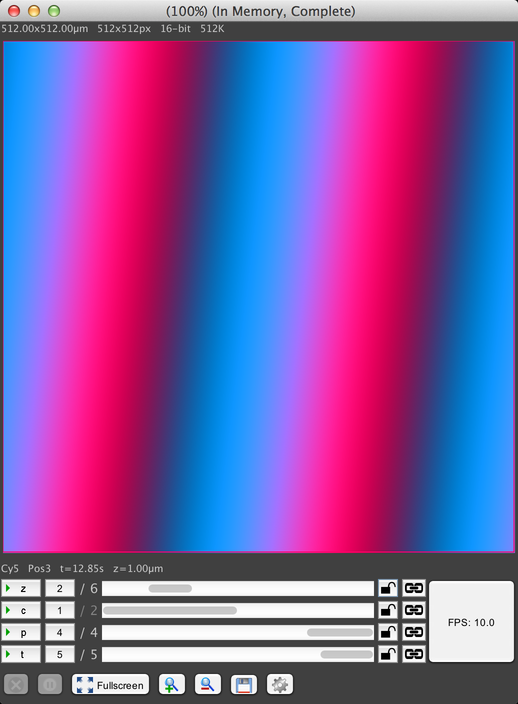
This window shows the output of your camera, including metadata about the image size, channel used, current stage position, etc. The image pixel display is on top, along with various metadata about the current image. Below that is the axis scrollbars that allow you to scroll through your dataset:

This dataset has four axes: Z (slice), channel, stage position, and timepoints. Each axis has the following controls, from left to right:
- The axis label button. Clicking on this button toggles animation of the axis, wherein the display automatically scrolls through the axis positions. For example, animating the Z axis will cause the display to scroll through all Z positions, scanning through the 3D volume acquired at this timepoint and stage position.
- The current position along the axis. In this screenshot, the Z axis is at position 2 of 6, channel is at 1 of 2, stage position is at 4 of 4, and timepoint is at 5 of 5. Clicking on this position indicator will pop up a text field to allow you to type the precise position you want to go to.
- A scrollbar that can be used to manually scroll through the positions.
- A lock icon, which can be used to prevent the display from modifying this axis while data is acquired. The lock icon has three states, which you can cycle between by clicking. When unlocked, the display will change the axis to reflect the most recently-received image during acquisition. When locked, the display will briefly show newly-acquired images, but “snap back” to the current position after a short delay. And when “superlocked” (with a red lock icon), the display will never change the axis.
- A link icon, which is only visible if you have at least two image windows open. See Linking Displays for more information.
The “FPS” button indicates the playback FPS when animating axes by clicking on the axis label buttons. Click on it to adjust the animation rate.
Along the bottom of the window is a row of buttons. The precise buttons available in an image window depend on whether it is an acquisition window or the Snap/Live window. Snap/Live has these three special buttons:
- Snap: Snap another image, replacing the image currently displayed.
- Live: Enable a live feed from the camera, continuously updating the displayed image as fast as possible. Click again to turn live off.
- Snap to Album: Snap a new image and add it to the “album”, which is an ad-hoc collection of images.
Acquisition windows have these two special buttons:
- Abort acquisition: after a confirmation dialog, will halt the acquisition.
- Pause acquisition: temporarily pauses the acquisition, allowing it to be resumed later. Note that acquisitions may only be paused if they are not Sequence Acquisitions. If your acquisition consists of multiple sequence acquisitions, then you can pause it in-between sequences (clicking once will automatically pause at the first opportunity).
Both window types have the following generic buttons:
- Fullscreen: toggle full-screen mode for this image window.
- Zoom In/Out: changes the scale of the image in the image window. This solely changes how many pixels in your computer monitor are used to display each pixel in the image; it does not change any hardware.
- Save: Save this dataset to disk
- Settings: access miscellaneous settings:
Image Window Settings
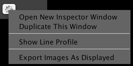
- Open New Inspector Window: this creates a new Inspector Window that you can tie to this image window.
- Duplicate This Window: creates a new image window that shows the same data as the current image window. This does not duplicate the data, just create a second “view” of it. While of limited utility for the Snap/Live view, this can be useful for larger datasets, as you can use the two windows to view different parts of the data side-by-side.
- Show Line Profile: brings up the Line Profile window.
- Export Images As Displayed: brings up the Export Images window.
Line Profile
The Line Profile shows you a graph of image pixel intensities along a line that you have drawn on your image. You can use ImageJ’s Line tool to draw a linear ROI on your image:
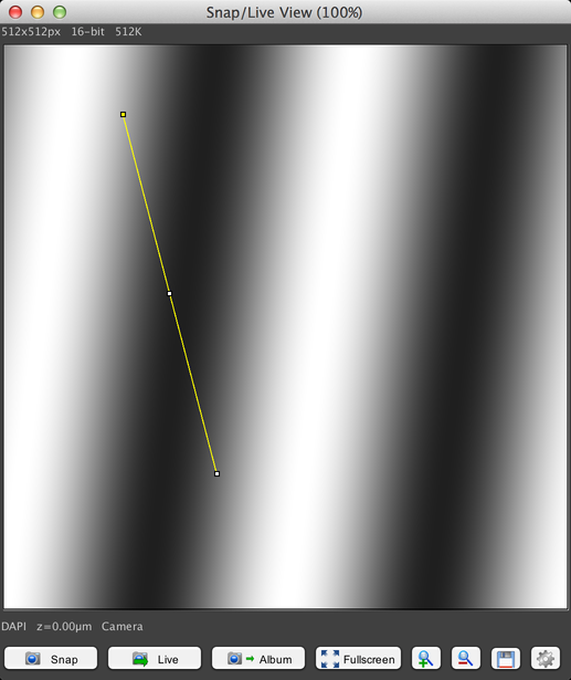
The Line Profile menu option will then show you a graph like this:
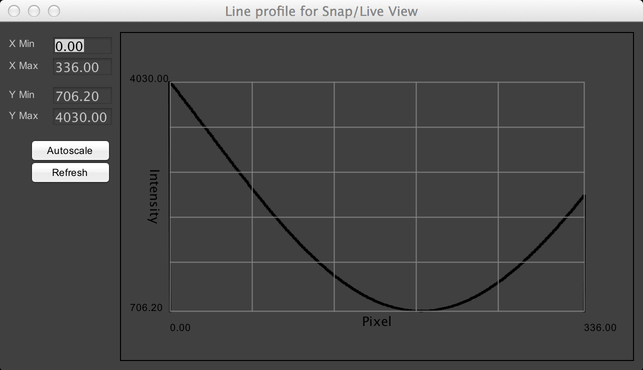
The profile will be automatically updated when either the image or the line is changed.
Export Images
This dialog allows you to export a series of image files that show your data as it is currently being displayed in the image window:

This can be useful for generating images or movies for use in presentations. It is not recommended that you use this dialog for preserving your raw data; instead use the “Save” button. This export system does not preserve image metadata, and because it uses your current contrast settings, will not necessarily preserve accurate image pixel intensities (it is a “lossy” storage system, not a lossless one).
Linking Displays
Oftentimes if you have multiple image windows open, it’s because you want to compare some similar aspect of them. µManager provides the ability to easily “link” displays together, which will cause changes to one display to be reflected in the other. Currently, two aspects of displays can be linked: their image coordinates, and their contrast settings.
Linking Image Coordinates
When you have two image windows open, and they both have at least one axis in common (for example, they both have a Time axis), you can link that axis by clicking on the link button in one of the image windows:

This will pop up a menu allowing you to link the window to other windows, by name. Select the other window’s name, and the two windows are linked on that axis; if you change the position of that axis in one window, it will automatically be changed in the other window as well.
Linking Contrast Settings
As with image coordinates above, if you have two image windows that have the same channel (for example, both have a channel named “DAPI”), then a link button will be added to the histogram in the Inspector window, just to the right of the channel color swatch:

Clicking on the link button allows you to link contrast with the other image window; adjustments made to the contrast in one window will then automatically be made to the other window as well.
Inspector Windows

The Inspector window is a versatile tool for helping your adjust and examine your image data. It floats on top of other windows, ensuring you can’t lose it. You can have multiple Inspector windows open at a time; to create a new one, select the “Open New Inspector Window” option from the Image Window Settings menu of any image window.
Each Inspector window will by default show information for the topmost image window. However, you can “tie” an Inspector to a specific window by selecting that window’s name from the “Show info for” dropdown menu.
The Inspector has multiple different panels, which are addressed individually below.
Histograms and Settings
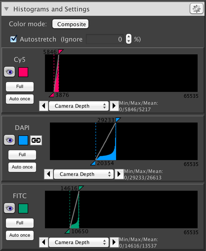
This panel shows information about the distribution of pixel intensities in your image, and allows you to adjust the brightness and contrast of your image displays. The above screenshot shows information for a three-channel dataset. Along the top are settings that apply to all channels; following that is a separate panel for each individual channel.
Global Histogram Controls
Histogram Gear Menu
- Gear menu (located in the “Histograms and Settings” header):

This menu provides access to some uncommonly-used settings:
-
- Logarithmic Y Axis: allows you to toggle the Y axis of histograms between a linear scale and a logarithmic scale.
- Calculate Standard Deviation: adds standard deviation to the list of statistics calculated about each image (see Image Statistics below). This can slightly reduce display framerates due to the extra calculations involved.
- Color Presets: select colors to use for all channels. µManager has two built-in color presets: an RGB set and a colorblind-friendly set (which is the default). Individual channels can also have their colors set manually.
- Histogram Update Rate: set how frequently histograms are recalculated. Histogram calculation is a CPU-intensive process and may slow down the rate at which images can be displayed on your computer. Calculating histograms less frequently or not at all can therefore improve framerates.
- Color mode:
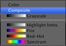
This dropdown menu allows you to choose how color is used when looking at grayscale images. You have the following options:
-
- Color: A single channel will be displayed at a time, using the color selected for the channel (see Channel Colors below).
- Composite: All channels are displayed simultaneously, using color blending.
- Grayscale: A single channel will be displayed at a time, using only black, white, and grays.
- False-Color LUTs: A variety of LUTs (Lookup Tables) are provided that apply false colors to a single channel at a time.
-
Autostretch: turns on or off automatic contrast calculation. When this is enabled, each time histograms are calculated, the “black point” is automatically set to the darkest pixel in the image, and the “white point” is automatically set to the brightest pixel.
- Ignore %: allows you to adjust the pixel values that are used for contrast settings when Autostretch is enabled, so that a value slightly “back” from the darkest/brightest pixel is used instead. For example, if this is set to .1%, then instead of using the brightest pixel, the 99.9%th brightest pixel will be used instead. This is useful if you have pixels whose values you want to ignore for purposes of calculating contrast.
Individual Channel Histograms
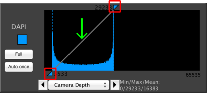
This shows a histogram for a single channel in your dataset. The most important function of this panel is to allow you to adjust how the channel is displayed by manipulating the brightness and contrast of the display. This does not affect the image pixel values; it only affects how they are shown on your screen.
To change the contrast, simply click and drag on the two triangles indicated by the red boxes in the above screenshot. By dragging the top box, you will change which pixel intensity indicates the “white point”, or maximum intensity. By dragging the bottom box, you will change the “black point”, or minimum intensity. By clicking and dragging on the line indicated by the green arrow, you will change the gamma, which is the curve used to interpolate between the black and white points. The default gamma is linear, but different gammas can be used to emphasize subtle variations in image intensities.
In addition to these abilities, the histogram provides the following other details:
Channel Colors

This sidebar indicates the channel name, and allows you to change the channel color by clicking on the colored square. The “Full” button automatically sets the black and white point to 0 and the maximum intensity that your camera is capable of providing. The “Auto once” button automatically performs a single autostretch, as if the “Autostretch” check box had been enabled.
If you have multiple channels available, then an eye button will appear to the left of the channel color swatch. Clicking it will turn on and off display of this channel when in composite view mode.
If there is another image window that has data for this channel, then a link button will appear to the right of the channel color swatch. See Linking Displays for more information.

This dropdown menu and associated zoom arrows allows you to set the X axis scale for the histogram, so you can “zoom in” on a specific range of intensities. The “Camera Depth” option (usually selected by default) will automatically set the scale to cover from 0 to the maximum intensity that your camera is capable of providing.
Image Statistics

While generating the histogram, µManager also calculates the minimum, maximum, and mean intensities of your image. If you have enabled the “Calculate Standard Deviation” option in the gear menu, then the standard deviation will also appear here.
Metadata
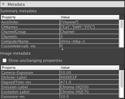
This panel shows various metadata about your dataset. The “Summary metadata” section shows metadata for the overall dataset that is not specific to any one image. The “Image metadata” section shows metadata that is specific to the currently-displayed image. If you are using a composite view mode, then the currently-selected channel is displayed.
By default, only metadata properties that have changed from one image to the next are displayed in the “Image metadata” table. If you want to view all metadata properties, click on the “Show unchanging properties” checkbox.
Comments
Comments Panel
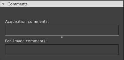
This panel shows any comments that have been included with the dataset. “Acquisition comments” shows information that is not specific to any one image, and “Per-image comments” shows information for the currently-displayed image. If you are using a composite view mode, then the currently-selected channel is displayed.
You can update the comments as you see fit. They are automatically saved whenever you make a change. Comments are saved to an “annotation file” that is stored alongside to, but separately from, the actual image data. Thus, changing the comments will not change your image data (nor will it change the “last modified” timestamp on the file).
Overlays
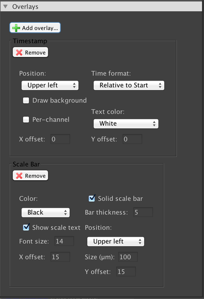
This panel allows you to add overlays that will be drawn on top of your image. Three overlays are available by default: a scale bar, a timestamp, and a pattern overlay which may be useful for aligning your sample with respect to your camera’s sensor or for performing cell counts. All overlays do not affect your image pixel data; they are simply drawn on top. If you want to obtain an image sequence that includes your overlays, use the Export Images dialog.
Multi-Dimensional Acquisition

The Multi-Dimensional Acquisition dialog is where you can set up complex data acquisitions. It’s Multi-Dimensional because the acquired dataset can have multiple axes of acquisition: Time, Z (depth), Channel (wavelength), and XYZ stage positions.
Timepoints
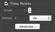
Specify how many timepoints to acquire. The “Interval” parameter specifies the minimum amount of time between the beginning of each timepoint in the acquisition. For example, if you specify an interval of 10 seconds, and the microscope is able to complete imaging a complete timepoint in 7 seconds, then it will wait for 3 seconds before starting the next timepoint. If the interval is shorter than the amount of time required to complete a full timepoint, then the next timepoint will begin immediately.
Custom Timepoint Intervals
If you click on the “Advanced” button, then you will be shown this dialog:
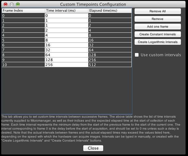
From here, you can manually specify precise times at which to start each timepoint, or automatically create a series of constant- or logarithmically-placed timepoints. Make certain the “Use custom intervals” checkbox is selected if you want to make use of this feature.
Sequence Acquisitions
Many scientific cameras are able to perform high-speed acquisitions, where the camera handles all timing details and operates at speeds potentially orders of magnitude faster than normal. µManager supports this functionality where available. If you have a camera that is capable of such “sequence acquisitions”, you can run a high-speed acquisition by ensuring that the “Interval” value is less than the exposure time you are using in your acquisition (for simplicity’s sake, you can set the interval to 0).
Sequence acquisitions are only possible if all of the hardware that needs to change during the acquisition is capable of being sequenced. Please see Hardware-based Synchronization in Micro-Manager for more information.
Z Stacks
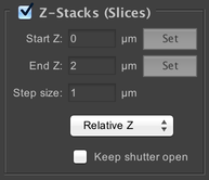
Specify how many different “slices” to take of the imaged volume. Use of this functionality requires you to have a Z stage. Each slice will be taken at a different focus level in the sample, as indicated by the “Start Z”, “End Z”, and “Step size” parameters.
The dropdown menu allows you to switch between Relative Z (pictured) and Absolute Z. In Relative Z, the Start Z and End Z values are relative to the current stage position. So for example, if you have focused on the center of your sample, a start of -5 and end of +5 would mean a 10µm stack centered on the current focus position. In Absolute Z, the Start Z and End Z values are in absolute coordinates (as determined by your stage device). You can use the “Set” buttons to set the current position as either the start or end. Thus to replicate the same 10µm stack, you would find your focus point, move 5µm up, click the “Set” button for Start Z, then move 10µm down and click the “Set” button for End Z.
If you select the “Keep shutter open” checkbox, then your shutter device will be left open during the course of the Z stack. This means that the microscope will not have to wait for the shutter to open and close after each image is collected, which can save time. However, your sample will be exposed to more light, which may cause undesirable bleaching.
Channels

Configure the different wavelengths of light you wish to acquire. In order to use channels, you must have created a special configuration group (see Config Groups) called the “Channel Group”, which you should select from the “Channel group” dropdown menu. To add new channels to the acquisition, click on the “New” button; you can then change which specific channel to use by clicking on the channel name in the table (in the “Configuration” column). Channels can be deleted with the “Remove” button, and re-ordered with the “Up” and “Down” buttons.
Each channel has its own row in the table, with corresponding settings:
- Use: enables or disables the channel in the acquisition as a whole. Unchecking this box is equivalent to removing the channel from the table entirely.
- Configuration: select which channel (from the available presets in the channel config group) to use.
- Exposure: set the camera exposure time to use when imaging with this channel.
- Z-offset: set an offset in microns to apply when imaging with this channel.
- Z-stack: if checked, this channel will be imaged once for each slice in the Z-stack (assuming Z-stacks are enabled); if unchecked, then only one image per Z-stack will be acquired, at the centermost slice position.
- Skip Fr.: skip certain timepoints with this channel. For example, if this is set to 1, then only every other timepoint will be imaged with this channel; if set to 2, only timepoints that are a multiple of 3 will be imaged; et cetera. This can be useful for channels that bleach easily.
- Color: set the color the channel will use in the image window associated with the acquisition.
If you click the “Keep shutter open” checkbox, then any shutter device involved in changing channels will not be closed in-between each channel. This means the microscope will not have to wait for the shutter to close and open each time the channel is changed, which can save time. However, your sample will be exposed to more light (with a potentially-irregular distribution among the different exposure wavelengths due to timing variabilities), which may cause undesirable bleaching.
Multiple Positions (XY)
MDA Stage Positions

Acquisitions can be configured to visit multiple stage positions, as set using the Stage Position List. All stage positions in the Stage Position List will be used.
Acquisition Order

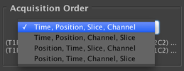
Allows you to configure the ordering of the different axes in the acquisition. You may choose whether you do every channel at each slice before moving to the next slice (“Slice, Channel” order) or do a complete Z-stack with a single channel before switching to the next channel (“Channel, Slice” order). And you may choose between doing a single timepoint at each stage position before starting the second timepoint (“Time, Position” order), or doing a complete timeseries at a single stage position, then a complete timeseries at the second stage position, etc. (“Position, Time” order).
In other words, the leftmost axis changes the fewest number of times, and the rightmost axis changes the most frequently. Depending on your hardware and the parameters of your experiment, different orders may be more desirable; the “Time, Position, Slice, Channel” order is most commonly used.
Autofocus

If you have an autofocus device, it can be configured to activate at each timepoint. If you set “Skip Frames” to a value greater than 1, then it will activate 1 in every N frames (e.g. setting it to 3 means using autofocus 1 in every 3 frames).
If multiple stage positions are enabled and autofocus is enabled, autofocus will automatically be used at each stage position, regardless of the “Skip Frames” setting.
You can click on the “Options” button to bring up the autofocus configuration dialog.
Save Images

Configure saving of data for your acquisition. The “Directory root” field indicates the directory in which saved data will be placed; each acquisition gets its own directory within that directory, named according to the “Name prefix” field. To simplify running multiple similar acquisitions, µManager automatically appends numerical suffixes to each acquisition. For example, if your directory root is set to “MyDocuments” and your suffix is “MyAcq”, then sequential acquisitions would be saved to “MyDocuments/MyAcq_1”, “MyDocuments/MyAcq_2”, et cetera.
You have two file format options: “Separate image files” and “Image stack file”. The former option will save each 2D image plane to a separate TIFF file, and create a metadata.txt file that contains metadata for each image. The latter will save the entire dataset into a single OME TIFF with bundled metadata. If the TIFF’s filesize would exceed 4GB, then it will be split into multiple TIFFs. Additionally, the Options Dialog allows you to save each stage position in a separate file, and also allows you to force µManager to generate a metadata.txt file even when using the Image Stack File format.
Acquisition Comments

You may type any extra comments here. These comments will be annotated to the data set. This is equivalent to writing comments into the “Summary Comments” section of the Comments Panel in the image window.
Other Buttons

- Close: closes the MDA dialog.
- Acquire!: starts an acquisition.
- Stop: stops the current running acquisition. A confirmation dialog will be shown first. Note that the acquisition can only be halted at specific, defined intervals. In particular, acquisitions cannot typically be halted in the middle of a sequence acquisition.
- Load…: Allows you to load an acquisition settings file. This will automatically populate all of the settings in the dialog based on the parameters in the file.
- Save as…: Allows you to save the current acquisition settings to a file. This file can then be used later with the “Load…” button, or with the Run Saved Acquisition button in the Quick Access Panel.
- from Image: When a dataset is loaded that contains MDA settings in its metadata, pressing this button will load this metadata into the MDA window.
- Multi MDA: Makes it possible to combine multiple MDA settings in one experiment.
Config Groups

Config Groups are groupings of related device properties. They provide a conveniente way to change the state of your microscope in a unified fashion. One common example is setting up a “channel group”: a config group used to change which wavelengths of light illuminate the sample and are seen by the camera. This could involve changing such properties as:
- Which light path to use (e.g. for switching between LED and laser light sources)
- What color of light to use, and its intensity
- What filters to place in the excitation beam and emission beam
Manually changing each of these properties via the Device Property Browser would be tedious and error-prone; instead, you can create a config group that changes each property together.
To create a new config group, click on the “+” button next to “Group”. To delete the selected group, click the “-“ button. Existing groups can be modified with the “Edit” button. Let’s create a new group now.
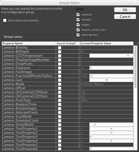
This window shows us a complete list of all properties for all devices in the microscope that µManager can change (if you checked the “Show read-only properties” checkbox, then non-modifiable properties would also be displayed). As we are using the demo hardware config, the properties shown in the above screenshot will not match what is shown on real hardware. But let’s create a config group that allows us to change the test pattern produced by the demo camera. Normally, the demo camera produces a straightforward sine wave pattern. Let’s check the “Camera-RotateImages” and “Camera-StripeWidth” properties. We also need to name the group; call it “TestPattern”:
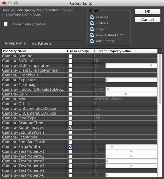
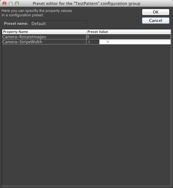
When we click OK, µManager will ask us to make a new “Preset” for this config group. A preset is simply some combination of settings for the device properties we just selected. We’ll use the current values as our first preset; just name it “Default”.
If we look at the config group panel in the main window now, we’ll see our new config group:
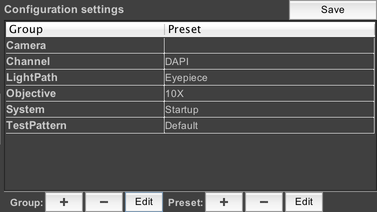
A config group with only one preset is not very useful, however, so let’s add another one. To do that, click on “TestPattern” to select the config group, then click on the “+” button next to “Preset”. This brings up the dialog to create another preset. This time, we’ll set RotateImages to 1, and change the stripe width to .1. Name the preset “Custom”:
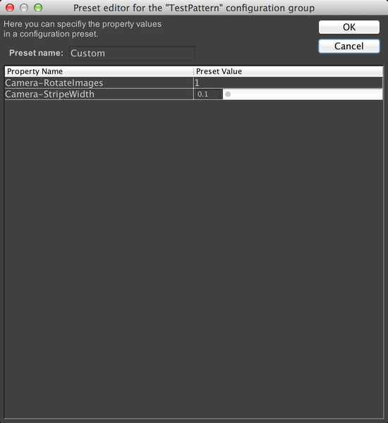
Now our preset has two options:

Go ahead and try snapping images and using live mode with each of the two presets. If you like, tweak the settings. When you’re done, make certain to click on the “Save” button at the top-right of the config group panel, so that your config groups will be available the next time you run µManager.
LabelState
A special note: many filter devices have both a “State” and a “Label” property. Typically the “State” is a numerical value indicating the number of the current filter position, and the “Label” is a human-convenient name for that position. Changing either State or Label will correctly set the hardware. Therefore, it is strongly recommended that _only one_ of State or Label (usually Label) be a part of the config group. Doing otherwise will cause µManager to attempt to set both properties whenever the channel is changed, which may cause slowdown or other problems.
Using the demo config file, you can see an example of how a channel config group should be set up by trying to edit the “Channel” config group. It contains properties for the dichroic label, emission filter label, and excitation filter label, but not the “State” properties for any of these.
Finally, you should never set the shutter device state in a config group. Let µManager handle manipulating the shutter device instead.
Stage Control
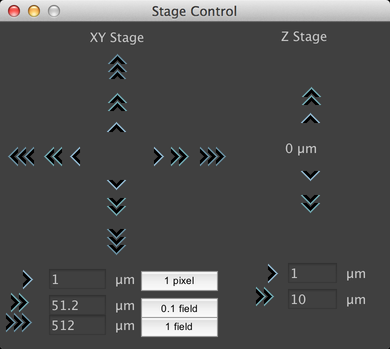
The Stage Control virtual joystick can be reached from the Tools Menu, or by clicking on the compass rose button in the main window. This window allows you to control the current stage position, by clicking on the “>” buttons. You can adjust the step size corresponding to each button using the text fields at the bottom. If you have performed a Pixel Calibration, then you can use the buttons to set default step sizes for the XY movement buttons of 1 pixel, a tenth of a field of view, and a full field of view.
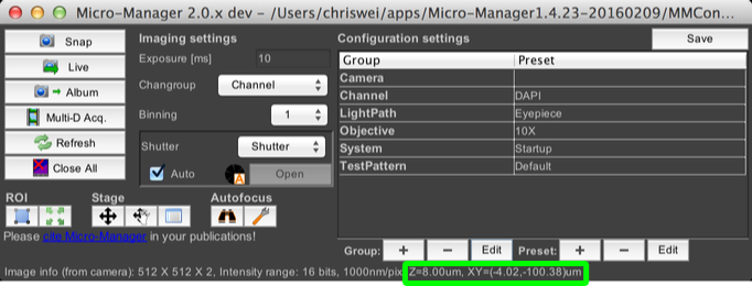
Note that the current stage position is always displayed in the main window, along the bottom:
Pixel Calibration
Pixel calibration refers to the process of determining how many microns are imaged onto each pixel of your camera. It is used any time you want to move the stage based on the current field of view; in particular, the Mouse Moves Stage mode, the Stage Control virtual joystick, and the Slide Explorer plugin all require valid pixel calibrations to work properly.
You can set up a manual pixel size calibration by going to the Tools Menu and selecting “Pixel Size Calibration”.
![]()
This dialog shows the demo config file, which already has several pixel sizes recorded in it. You can add new ones with the “New” button:
![]()
This works much like modifying a config group: select a new name for the pixel size (the default shown here is “Res3”), indicate the pixel size, and then select which device property or properties correspond to the new pixel size. When those properties change, µManager will automatically update the current pixel size. For the demo config, the only relevant property is the current objective.
If you are creating a new config file, and thus do not have any pre-set pixel sizes, then you will instead be shown a dialog like the one used to create a new config group, which we will walk through now. For purposes of this tutorial, the pixel sizes built into the demo config were all deleted instead.
![]()
Click the “Use” checkbox to select the device properties that impact the pixel size on your microscope. We’ll just select the “Objective-Label” property. As with normal config groups, we do not want to add both the “State” and “Label” properties to the same config group; they are redundant.
![]()
This creates a new pixel size config group; we can then add new pixel sizes from here as before.
Stage Position List
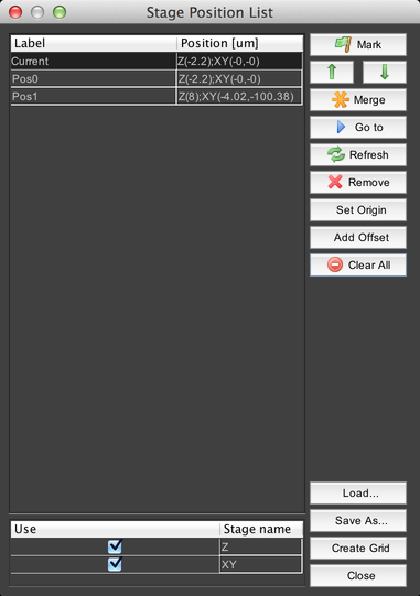
This dialog allows you to mark sets of stage coordinates and return to them later, for example during an acquisition.
At the bottom of the dialog is a list of all of the stage devices that µManager knows about. Clicking on the “Use” checkbox will enable or disable recording their positions – so for example, if the Z stage is disabled, then only XY positions will be recorded.
Click on the “Mark” button to record a new position using the current stage coordinates for all active stage devices. The up and down arrows will re-order the stage position list.
The “Merge” button allows you to overwrite coordinates in a marked position using the current coordinates of a stage device.

For example, selecting the “Merge with XY current position” option would cause the XY coordinates in the stage position to be overwritten by the current XY stage coordinates.
The “Go to” button moves the stage(s) to the coordinates of the selected position. The “Refresh” button updates the “Current” position coordinates in case they have changed. “Remove” deletes the selected stage position, and “Clear All” deletes all stage positions.
The “Set Origin” button sets the current stage position as the “zero point” reference from which all stage coordinates are derived. For example, if you set the origin when at XY = (100, 50), then your stage position will be indicated as (0, 0), but it will be the same location as previously indicated. Note that setting the origin requires re-homing the stage, which can move it; be certain that this will not cause the stage to “crash” into the objective lens or anything else. You will be given a warning dialog prior to homing the stage.
The “Add Offset” button allows you to shift the position of the currently-selected stage positions. You can use this, for example, to correct for accidentally bumping the sample holder.
Stage position lists can be saved to disk and then loaded later using the “Save As…” and “Load…” buttons.
Finally, the “Create Grid” button allows you to quickly create a 2D grid of stage positions:
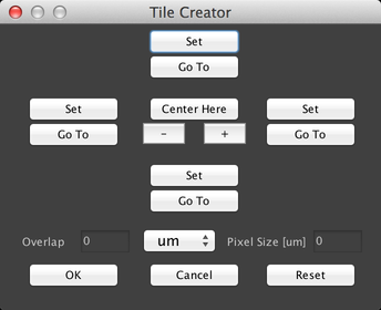
This can be useful for “mapping” large samples that don’t fit into a single camera field of view. To use this dialog, you must have set up a Pixel Calibration.
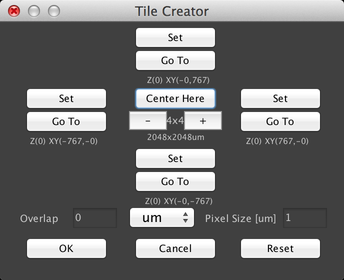
There are two primary ways to use this dialog. The first is to center the grid on the current stage position and just create a square grid. To do this, click on the “+” or “-“ buttons to set the size of the grid, and then click on the “Center Here” button:
The second method is to set the boundaries of the grid by moving the stage, for example with the Stage Control virtual joystick. Click on the “Set” buttons to set the X and Y “top” and “bottom” positions:
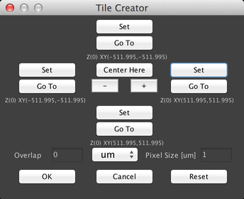
The rectangle specified by these set points will then be “filled in” with stage positions so that the entire region is imaged.
Both methods of creating a grid allow you to specify how much overlap there should be between adjacent fields of view, by using the “Overlap” field. Overlap can be specified in microns, pixels, or percentages.
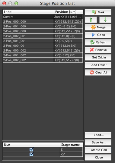
When you click “OK”, the grid will be created as a list of stage positions:
Device Property Browser
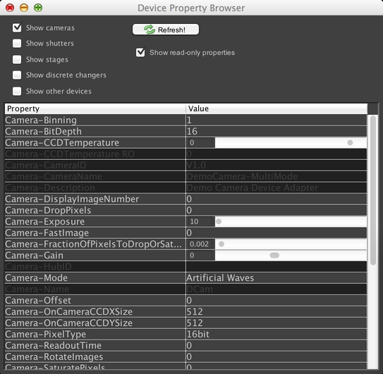
The Device Property Browser, reachable from the Config Menu, allows you to manually control your microscope hardware. It provides a complete list of all controllable properties of each device in the microscope that has been configured to work with µManager. This gives you a lot of power over the system; however, this dialog is typically not very convenient for common use. If you have properties that you routinely need to modify, you should consider setting up a config group instead.
To control a piece of hardware, find its name in the table, and find the name of the property you want to modify. Then simply input the new value; values are set immediately. Some values are dropdown menus; some have a range of allowed values (indicated by sliders). Some properties are “read-only”, which means they cannot be modified by the user; these are typically used for general information about the device (like serial numbers) or for readouts from sensors (like the camera CCD temperature property in the screenshot).
You can toggle visibility of these read-only properties using the “Show read-only properties” checkbox. You can also filter the list of visible devices using the checkboxes at the top, to show e.g. only camera devices.
The Device Property Browser is not automatically updated when device properties are changed elsewhere in the system (for example, due to changes to a config group). Click the “Refresh” button to manually update it instead. It automatically refreshes itself every time you use it to change a property value.
Hardware Config Wizard
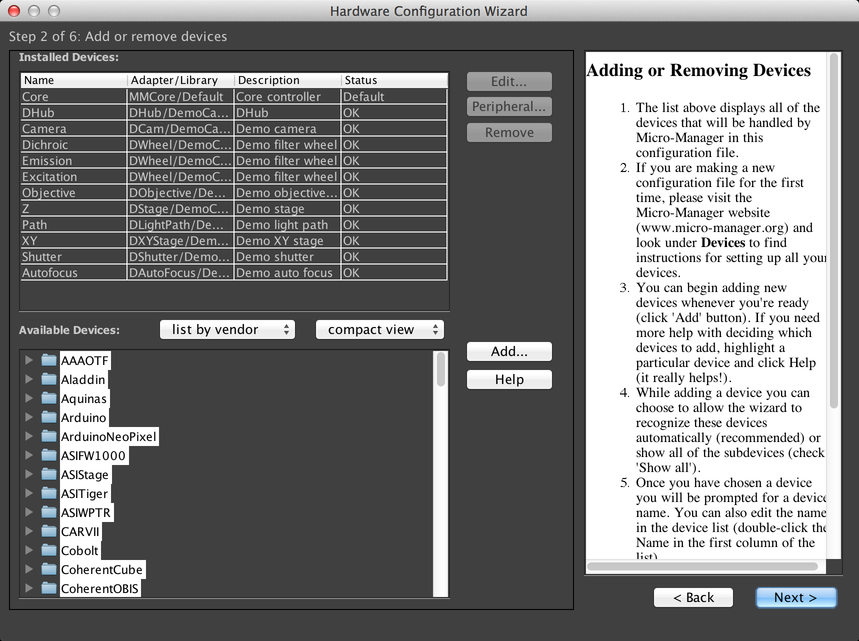
The Hardware Configuration Wizard, reachable from the Config Menu, will walk you through configuring your hardware to work with µManager. It has its own built-in documentation, which will not be recapitulated here.
Menus
µManager places some important functionality in its menu system. On Windows and Linux, the menu bar is located in the main window. On OSX, the main window must have focus for the menu bar to show the µManager menus.
File Menu
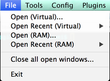
The File menu contains options for opening data files, closing open image windows, and quitting µManager.
When you use the “RAM” option to open a file, the complete contents of the file are loaded into memory. This makes access and analysis of data quick, but it takes longer to load the file at the outset, and may use substantial (indeed, prohibitive) amounts of system memory if you try to load an especially large dataset. In such cases, you should use the “Virtual” option to open the file instead. “Virtual” mode loads only the portions of the file that are needed at any given time. Thus, loading data is substantially faster at the beginning; however, if you need to perform detailed analyses, µManager may end up re-loading the same data over and over again, which results in a net performance loss.
The “Close all open windows” command behaves identically to the Close All Image Windows button in the main window.
Tools Menu
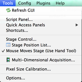
The Tools menu contains a variety of miscellaneous tools.
- Refresh GUI: updates the user interface to reflect the current state of the microscope hardware.
- Script Panel: opens the Script Panel.
- Quick Access Panels: access the Quick Access Panel system.
- Shortcuts: brings up the Keyboard Shortcuts dialog.
- Stage Control: opens the Stage Control window.
- Stage Position List: opens the Stage Position List window.
- Mouse Moves Stage: toggles the ability to use ImageJ’s hand tool to move the stage in the Snap/Live view. This is the same as clicking on the hand icon in the main window’s miscellaneous buttons.
- Multi-Dimension Acquisition: opens the Multi-Dimensional Acquisition window.
- Pixel Size Calibration: opens the Pixel Calibration dialog.
- Options: opens the Options Dialog
Options Dialog
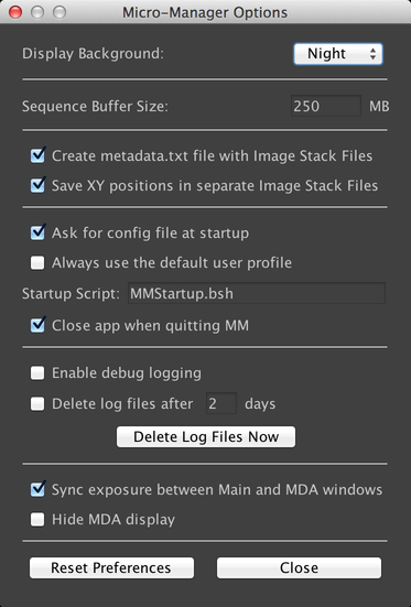
This dialog, reachable via the Tools Menu, allows you to configure various aspects of µManager.
- The “Display Background” allows you to select between a traditional black-on-white display mode, and a “Night” mode that has lower contrast and is more comfortable to use in darkrooms. Most screenshots in this guide use the “Night” mode.
- The Sequence Buffer Size determines how much RAM is allocated to transient image storage when performing acquisitions. See the Configuration Guide for more information.
- “Create metadata.txt file” ensures that every data file that µManager creates will include an additional text file that contains all image and acquisition metadata. Without this option, if you save data using the “Image stack file” format, metadata will be encoded into the OME TIFF file, but will not otherwise be available.
- “Save XY positions separately” creates a separate OME TIFF file for each stage position in acquisitions that use multiple stage positions. Without this option, all images for an acquisition will be stored in the same OME TIFF file.
- “Ask for config file at startup” prompts you for a config file in the Intro Dialog. If it is unchecked, then the currently-selected config file will be used by default.
- “Always use the default user profile” disables the ability to select a user profile in the Intro Dialog.
- “Startup Script” is a Beanshell script that will automatically be executed when the program launches. See the Script Panel for more information.
- “Close app when quitting MM” will cause the program to exit when µManager is closed. If this is disabled, then when you close µManager, ImageJ will continue to run.
- “Enable debug logging” adds extensive additional logging to the program. These logs are stored in the “CoreLogs” directory of your µManager installation.
- “Delete log files” will automatically delete files from the CoreLogs directory that are older than the indicated number of days.
- “Sync exposure between Main and MDA windows” will cause the exposure time in the Main Window and the exposure time for the currently-selected channel in the Multi-Dimensional Acquisition dialog to be synchronized, so that changes in one will be reflected in the other.
- “Hide MDA Display” causes acquisitions to not create an image window when they execute.
Config Menu
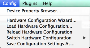
The Config Menu provides options for interacting with your system’s hardware. It provides access to the Device Property Browser and the Hardware Config Wizard, and also allows you to save and load configuration files. “Reload Hardware Configuration” causes µManager to unload and then reload the current configuration. Any time a hardware config file is loaded, µManager’s GUI is refreshed to reflect the current hardware state.
Plugins Menu
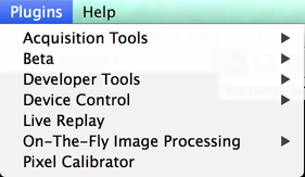
The Plugins menu provides access to various plugins that extend µManager’s capabilities in various ways. See Plugins for more information.
Help Menu
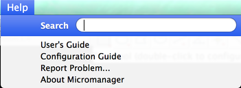
The Help Menu provides access to support resources.
- User’s Guide: links to this document.
- Configuration Guide: links to Micro-Manager Configuration Guide
- Report Problem: allows you to submit a Problem Report
- About Micromanager: brings up a dialog containing some information about µManager.
Problem Reports
Problem Reports are a way for you to send detailed information about malfunctions or errors in your system to the maintainers of µManager. See the FAQ for more information. Please note that the µManager maintainers cannot promise to provide assistance to users who are not subscribed to their support services.
Plugins
Plugins are extensions of µManager’s capabilities. There are various types of plugins that are accessible in different contexts, but the primary type of plugin is available via the Plugins Menu. This document will not try to explain every plugin in µManager, but it will cover some of the important ones. Plugins has information about more plugins.
Pixel Calibrator
![]()
In some situations, merely knowing the pixel size is not enough; you need to know exactly how a portion of your sample maps onto the camera’s field of view, including rotation, scaling, and other “transformations”. The Pixel Calibrator plugin will determine what this transformation is by taking images of your sample while moving the XY stage. Having a valid pixel calibration is required in order to use the Slide Explorer plugin.
Slide Explorer
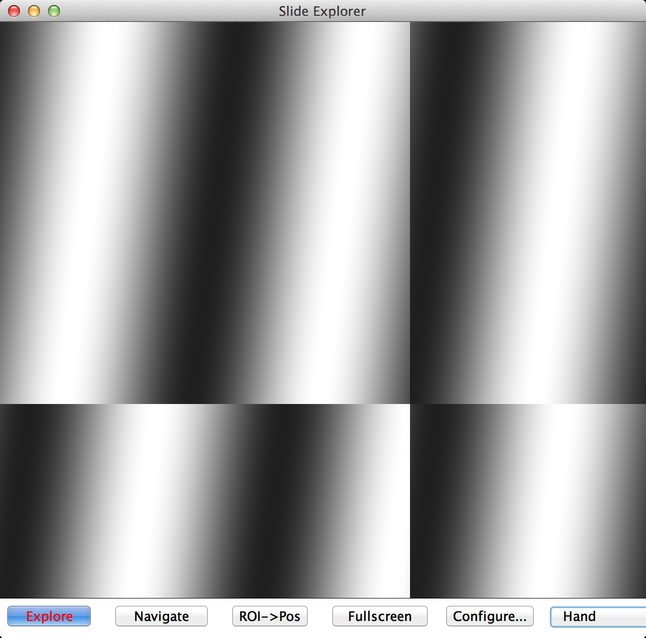
Slide Explorer (reachable from the “Acquisition Tools” submenu of the Plugins menu) is useful for “mapping” out large samples that cannot fit into your camera’s field of view, or for seeking out items of interest in a sparse sample. In order to use Slide Explorer, you need to have performed a pixel calibration.
Slide Explorer will continuously move the stage and image the sample, until the current view area is completely filled in. To guide the exploration, you can grab the view using ImageJ’s hand tool and drag it, to expose unexplored regions. You can also zoom in and out using ImageJ’s magnifying glass tool or by clicking on the “+” and “-“ buttons.
When you are done mapping your sample, you can switch from “Explore” mode to “Navigate” mode. In Navigate mode, clicking using ImageJ’s hand tool will move the stage instead of changing the view.
If you want to mark stage positions for more detailed imaging, you can draw an ROI (Region of Interest) using ImageJ’s various ROI marking tools, then click the “ROI->Pos” button. This will generate enough stage positions to fully-cover the ROI you have drawn.
Unfortunately, at this time it is not possible to save the data gathered by Slide Explorer. You will need to perform an acquisition using sites generated by Slide Explorer instead.
HCS Site Generator
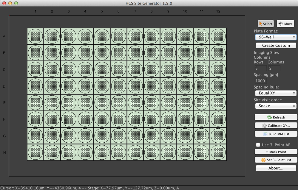
This plugin (reachable from the “Acquisition Tools” submenu of the Plugins menu) simplifies the process of surveying large samples like 96-well plates. It can mark stage positions for you, which can then be visited using the Multi-Dimensional Acquisition system.
Many different multi-sample systems are available, including both well plates and slides. To change the format, select an option from the “Plate Format” dropdown menu. You can also define your own format using the “Create Custom” option, and then use that format via the “Load custom…” option in the dropdown menu.
The sample display is interactive in two ways. First, if the “Select” button is pressed, you can select wells or slides by clicking and dragging the mouse. Only selected samples will have stage positions generated for them. Second, if the “Move” button is pressed, you can click anywhere in the display to move the stage to the specified location.
µManager will create a rectangular grid of sites in each sample region according to the “Rows”, “Columns”, and “Spacing” fields. There are three spacing rules: the default “Equal XY” uses only one spacing value, while “Different XY” lets you specify both X and Y offsets. Finally, “Field of View” lets you tile each sample based on the camera’s field of view. Using this option requires you to have run the Pixel Calibrator plugin.
“Site visit order” will determine the order in which stage positions are listed and thus the order in which µManager will visit them during an acquisition. The default “Snake” order travels to the right on odd-numbered rows and to the left on even-numbered rows, minimizing travel time. The “Typewriter” order instead always travels to the right.
When you have set the site grid parameters and selected your wells, click the “build MM List” button to create the stage positions.
The “Calibrate XY” button allows you to set the origin (the position indicated by (0, 0)) of the XY stage. “Refresh” will rebuild the GUI after changes to the hardware.
Finally, the plugin includes an option to automatically set the Z position of marked positions by interpolating between three in-focus points you have set. Check the “Use 3-Point AF” checkbox to enable this functionality. Then move the stage to three widely-spaced points, focusing at each and then clicking the “Mark Point” button. This will add the point to the Stage Position List. Once you have three in-focus points in the list, click the “Set 3-Point List” button. µManager will fit a plane through the three points, and use that to derive the in-focus altitude of each point generated when you click the “Build MM List” button. Once you have generated this plane, you should delete the points from the position list so they are not used for imaging later.
Quick Access Panel
The Quick Access Panel system allows you to create customized windows that allow you to easily access the controls you need most frequently. You can access the Quick Access Panel system from the Tools menu.

You can have multiple Quick Access Panels at the same time; select the “Create New Panel” option to make new ones, or the “Delete” option to delete one you no longer need. Below that is a list of all Quick Access Panels – there’s only one in this case, named “My Settings”. If you want to save your panel setup for re-use or sharing with others, use “Save Settings”; conversely, if you want to load someone else’s settings, use “Load Settings”. Note that your personal Quick Access Panels are always remembered from one session to the next, so you do not need to use these options just to preserve your setup.
Here is an example Quick Access Panel:
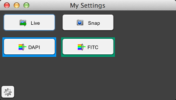
This panel has buttons for snapping images, turning live mode on and off, and setting the channel to either DAPI or FITC. To customize the panel, click on the gear button, and it will expand the panel:
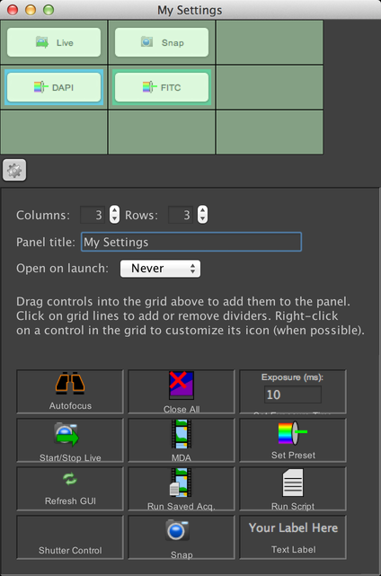
In this mode, you can set the size of the panel’s grid (the default is 3x3 cells), change the panel’s title, and decide whether or not the panel should be automatically opened when µManager launches. Finally, you can add or remove controls to/from the grid. To add a control, simply click on its icon in the bottom grid, and drag the icon into the grid where you wish to place it. You can also pick up controls that you have already added, and move them to new locations. If you want to remove a control that’s already in the grid, click on it and drag it out of the grid.
The following is a list of some of the less-obvious controls you can add to your panels.
MDA
This opens the Multi-Dimensional Acquisition dialog.
Set Preset
Allows you to select an option from one of your Config Groups. When you drop this control into the grid, it will prompt you for which config group, and which preset from that config group, that you want to set when the button is pressed. The “DAPI” and “FITC” buttons in the example screenshot are Set Preset buttons.
Run Saved Acquisition
Allows you to run an acquisition at the press of a button. You need to have set up the acquisition beforehand via the Save As button in the Multi-Dimensional Acquisition dialog.
Run Script
Allows you to run a Beanshell script at the press of a button. See the Script Panel for more information.
Script Panel
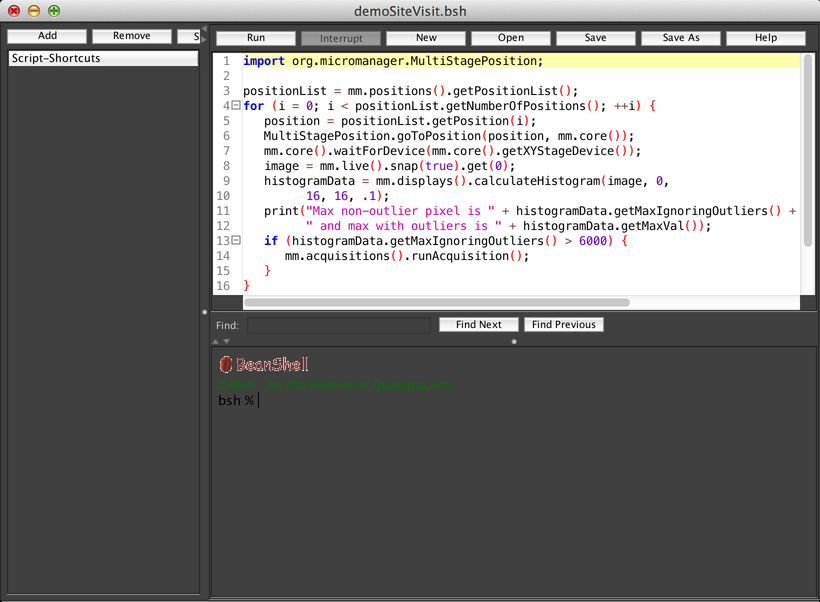
The Script Panel (reachable from the Tools menu) allows you to write scripts that implement custom behaviors. You can use scripts to run customized acquisitions, analyze your data, set up your hardware in a specific way, and more. Scripts are written in the Beanshell programming language, which is a simplified dialect of Java.
The main text editor area on the top is where you write your scripts. You can run a script using the “Run” button (and, while it is running, use the “Interrupt” button to attempt to halt it). Scripts can be created, loaded, and saved using the “New”, “Open”, “Save”, and “Save As” buttons.
Below the text editor is a REPL, or “Read-Eval-Print Loop”, where you can execute Beanshell commands one at a time. For example, to snap a single image in µManager, you can input the command “mm.live().snap(true);” (without the quotation marks).
If you want to write your own scripts, you should read the API, plugins and other documentation at the µManager 2.0 index. In particular, you can access the Studio object via the pre-set variable “mm” (for example, “mm.displays().show(image)” to display an image), and you can access the MM Core via the “mmc” variable (for example, “mmc.getChannelGroup()”). These two objects are your primary access points for controlling µManager.
On the left-hand side of the Script Panel is a list of shortcut scripts. Click the “Add” button to add the current script to the list; you can then switch between scripts by clicking on them.
Keyboard Shortcuts
Click on the “ShortCuts” button in the Script Panel (or select the “Shortcuts” option from the Tools menu) to bring up the keyboard shortcuts dialog:
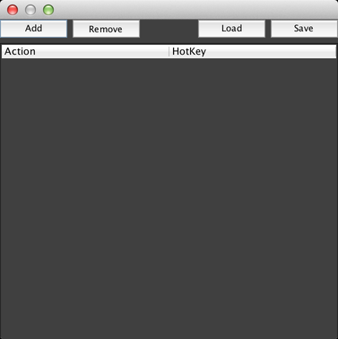
This dialog allows you to run scripts by pressing keys on your keyboard (assuming that you are not entering text into a text field). Click on “Add” to add a new keyboard shortcut, which will add a row to the table:
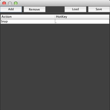
The default action is always “Snap”, but by clicking on that action, you can get a dropdown menu of other actions you can perform:
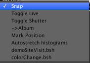
This menu includes several built-in actions, as well as the scripts that we added to the shortcut scripts in the Script Panel earlier.
Click on the row in the “HotKey” column and press the key you want to associate with this action. From now on, whenever you press that key, your script will be executed.
You can save and load your shortcut settings to/from files using the “Save” and “Load” buttons. This is only necessary if you want to share your shortcuts with others, as they are automatically remembered for you by the program.
On-The-Fly Image Processing
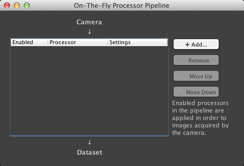
µManager supports the ability to manipulate images as they are being acquired, through its On-The-Fly Image Processing system. This system creates a “pipeline” of image processors during any data acquisition. Images emerge from the µManager Core and are inserted into the first processor; the output of that processor is fed into the next, and so on. You can access this window via the “On-The-Fly Image Processing” submenu of the Plugins menu.
µManager has four built-in processors:
Flat-Field Correction
This processor can correct for systematic sources of error in the images output by your camera, by applying correction files you have generated previously. See Flat-Field Correction for more information.
Image Flipper
Image Flipper can rotate and/or mirror images output by your camera, which may be helpful for aligning them with the eyepiece or for matching up coordinate systems with your well plates.
Split View
Split View takes a single image from your camera and cuts it along either vertical or horizontal lines, assembling multiple images from the cut result. This is useful, for example, if you have a setup that images multiple channels onto the same camera field of view simultaneously. Split View can do 2-, 3-, 4-, or 5-image splits, and you can layer multiple Split View plugins to create both horizontal and vertical splits.
Image Saver
Image Saver allows you to save data from any point in the pipeline. This can be helpful if you wish to preserve the raw data of your acquisition prior to performing any modifications to it.
