This page is a brief tutorial to build a very simple circuit to control laser shutters, using an Arduino board. In this particular case, there are two shutters, coupled with two Cobolt lasers (belonging to Micro-Manager supported devices), so is possible to facilitate use of lasers with a GUI panel, generated by a Beanshell script. The following procedure is generally useful to build a circuit with two BNC connectors, in order to supply HIGH/LOW voltage state to TTL devices.
The software GUI panel for control easily laser power and shutter can be found in Cobolt laser subsection GUI panel for Cobolt laser control.
For circuit, the following materials are required:
-An Arduino board;
-1 A/B USB cable (to connect Arduino board);
-2 BNC connectors;
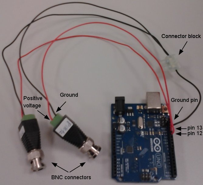
-5 wires (which length must be enough to go from Arduino board to laser shutters), of different color to make easy their recognition (I choose 2 red for positive voltage and 3 black for ground connection, see picture below);
-1 connector block.
For info about board working specifications read Arduino page. It’s only necessary to load the firmware source code in Arduino board and this will let set different state to set pins from 8 to 13 in HIGH/LOW state.
If you choose pin 12 for control of first laser shutter and pin 13 for the second, is possible open and close the shutters, just setting Arduino state to value “16” (pin 12) or “32” (pin 13).
In order to build the cicuit:
- strip the ends of a red wire and connect it to positive (+) pole of a BNC connector and to pin 12;
- strip the ends of the second red wire and connect it to positive (+) pole of the other BNC connector and to pin 13;
- strip the ends of 2 black wires and connect them to negative (-) pole of two different BNC connectors, after connect other ends togheter on a side of connector block;
- strip the ends of fifth wire and connect it to connector block and to ground pin of Arduino board.
This is the picture of circuit.
Finally connect Arduino to pc with USB cable and include it in hardware configuration wizard.
Check if circuit works with a voltmeter:
- measure voltage between internal pin and external structure of BNC connectors before setting any “Arduino state” in “Device/Properties Browser…”; this must give value zero Volt.
- measure voltage in same way for BNC connected at pin 12, after setting of “Arduino state” value 16 and opening “Arduino shutter”; this must give value around 5 Volt;
- check in the same way BNC connected at pin 13, setting instead “Arduino state” value 32; this must give value around 5 Volt;
Note: to invert HIGH/LOW state of BNC output use “Inverted logic” insted of “Normal” during Arduino board configuration.
Note: for more info about Arduino output voltage and technical specifications visit Arduino project webpage.
Rocco D’Antuono