PI GCS 2 Adapter for XY- and Z motion
|
Summary: |
Interfaces with Physik Instrumente (PI) GCS Controllers for X/Y and Z motion |
|
Author: |
Rachel Hammer, Steffen Rau (PI) (based on code by Nico Stuurman and Nenad Amodaj) |
|
License: |
BSD |
|
Platforms: |
All platforms (serial interface) / Linux and Windows (uses PI GCS software modules) |
|
Devices: |
Stage (XY and Z) |
|
Example Config File: |
None |
|
Micro-Manager version: |
1.4 |
The “PI GCS 2” adapter is compatible with most current PI controllers. PI piezo controllers can also be controlled with analog input (via analog DAC board driver in Micro-Manager). PI GCS 2 provides the same features as the previous “PI GCS” adapter. If you are using a PI device for the first time, please do not use the PI GCS adapter but use “PI GCS 2”.
The adapter uses two different connection modes:
- serial connection of Micro-Manager, thus being platform independent
- PI GCS modules (DLL or shared-object) for Linux and Windows
The PI GCS modules are needed if controllers are used where the GCS command interpreter is implemented in the software module (e.g. C-843, E-710 and Mercury (C-863/663) with native firmware), or if the controller does not provide an RS-232 interface (e.g. E-761 that uses PCI).
Device Types
The adapter appears as “PI_GCS_2” library in the Hardware configuration. Basically it provides four different devices:
- PIZStage
- PIXYStage
- PI_GCSController_DLL
- PI_GCSController
For some controllers special instances of the “controller” devices are provided. Here some of the values are already pre-set:
- C-843 (using the C843_GCS_DLL and only available for Windows)
- C-663.11 (using serial connection)
- C-863.11 (using serial connection)
- C-867 (supports all different C-867 models, e.g. C-867.160, C-867.260, …)
- E-517/E-545 (using serial connection)
- E-710 (using the E7XX_GCS_DLL module, not available for MAC OS X)
- E-712 (using serial connection)
- E-753 (using serial connection)
The controller devices handle the communication with the PI controller. The two “stage” devices are the XYStage and ZStage devices used inside Micro-Manager and represent the axes connected to the PI controller. Each stage device needs a controller device to communicate. So you always have to add at least two devices (see examples below).
Please note: many PI devices use the RTS/CTS lines for hardware handshake. If using a different cable, please check if your device needs hardware handshake and if the cable has these lines connected.
Configuration
First you have to add a controller device for each PI controller you want to control by Micro-Manager. Give it a meaningful name, since the stages need this name to call the controller. After this you add the stages you want to use in Micro-Manager. Note that each controller can have as many stage devices as there are physical axes connected. E.g. one C-843.41 controller with 3 motorized stages can be used as one XYStage and one ZStage inside Micro-Manager, or you can use a 3-axis piezo stage connected to an E-712/710 as XYStage and ZStage. You can also use two single axis controllers to control one XY stage.
Communication with the devices is implemented in two different ways:
- using the built-in serial (RS-232) communication of Micro-Manager - no other software modules are required. This is possible for all platforms supported by Micro-Manager. Implemented by “PI_GCSController”.
- using PI’s modules (DLLs) - this allows connecting to RS-232 and PCI but is limited to Windows. Implemented by “PI_GCSControllerDLL”.
Here is a detailed overview over the different properties of the 4 basic devices. If you have selected one of the predefined controllers not all properties are available as they have already been pre-set.
PI_GCSControllerDLL:
- DLL Name: file name of DLL or shared object. On Windows you can find this e.g. in the version information of PIMikroMove. In most cases this is “PI_GCS2_DLL.dll” if you use 32bit version of Micro-Manager or “PI_GCS2_DLL_x64.dll” if you use 64bit version. The DLL must be copied to Micro-Manager’s installation directory.
- Interface Type: Type of interface used for connection. Currently “PCI”, “RS-232”, “USB”, and “TCP/IP” are implemented. NOTE: If you select “RS-232” you must not configure this serial device in Micro-Manager, since the PI DLL/shared object needs exclusive access.
- Interface Parameter: This is a string where the single values
are separated by “;”. For “RS-232” this is “
; ”. If you want, for example, to connect a PI device on COM1 with 57600 baud, type "1;57600". On Linux, "1" is mapped to "/dev/ttyS0", "2" to "/dev/ttyS1", and so on. For "PCI" this is a single integer with the board ID. For "USB" this is a description of the device, e.g. the serial number as displayed in PIMikroMove's connection window. For "TCP/IP" this is the IP number of the controller, followed by ":", followed by the port number, e.g. "192.168.0.25:50000".
PI_GCSController:
- Port: serial port used to communicate with the device. If you use the VCOM driver you can use PITerminal or PIMikroMove to find out which COM port to use.
- um in default unit: Since PI controllers either work in mm/deg or µm/µrad and Micro-Manager uses µm, you need to define the factor to get µm from the default unit of the controller. For piezo controllers using µm this is typically 1, for motor controllers with mm this is “0.001”.
PIZStage:
- Axis: Name of axis
- Controller Name: Name of the controller as defined in the hardware configuration wizard of Micro-Manager
- Limit_um: define a limit for the Z stage in µm. Range is
0…
- Stage: stage type (see notes below)
PIXYStage:
- Axis X: Name: Name of the axis to be used as X axis
- Axis X: Stage: Stage type for X axis (see notes below)
- Axis X: Homing Mode: Which feature to use for homing the X
stage. Can be one of:
- “FNL” or “MNL” for negative limit switch
- “FPL” or “MPL” for positive limit switch
- “FRF” or “REF” for reference switch.
- ”” for stages with absolute position sensors (most piezo stages)
- Axis Y: Name: Name of the axis to be used as Y axis
- Axis Y: Stage: Stage type for Y axis (see notes below)
- Axis Y: Homing Mode: See “Axis X: Homing Mode”
- Controller Name: Name of the controller as defined in the hardware configuration wizard of Micro-Manager
- Controller Name for Y axis: If the Y axis is connected to a different controller, you need to enter its name here. If this is empty, the same controller is used for X and Y.
The stage devices have a property called Stage. For PI_GCSController type controller this property is ignored. This is only relevant for stages connected to a PI_GCSControllerDLL controller type which cannot store the stage parameters, e.g., C-843. If relevant, enter the name of the stage type for this property. If the controller can store the stage type parameters, it’s strongly recommended to configure everything with PIMikroMove (see below) and leave this property empty.
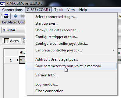
If the controller is able to store the stage parameters, use PIMikroMove to configure the parameters: When the stage configuration was sent to the controller with the “Assign Stages” dialog window, you can afterwards call “Save parameters to non-volatile memory” in the corresponding controller menu (see figure below). The password used is usually “100”. Please see the user manual of the controller for details.
Homing of the stages
For XYStages Micro-Manager supports the homing of the stages in the Axes list.
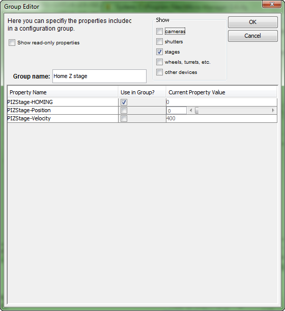
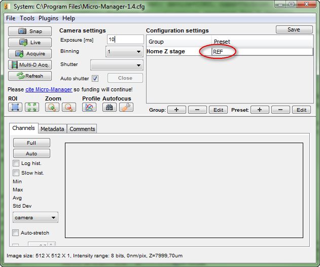
Since ZStages currently do not support homing, but stages with incremental sensors need to be homed, there is a “homing” property for Z Stages which can be set during runtime: For each ZStage create a new “Configuration Group”, name it “Home Z Stage”, select “stages” in the “Show” field and add the “HOMING” property by selecting “Use in group?” for the corresponding row. Then you have a new GUI element. When you now enter “FRF”, “REF”, “FNL”, “MNL”, “FPL” or “MPL”, the Z Stage will move towards the reference (REF or FRF), the negative (MNL or FNL) or positive (MPL or FPL) limit switch (see figures below). NOTE: This is a workaround. The stage may take several seconds to reach the target. Most likely this will result in an error message “device times out”. Please close this error message AFTER the stage has finished. Then you should be able to continue using this ZStage.
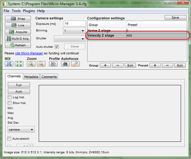
Changing velocity
To change the velocity of the stage you can create an additional
configuration group and select the property “Velocity” of the stage.
Then you can change the velocity of the stage at any time in the
corresponding GUI element.
Controller Joystick / HID Control
To some controllers a joystick can be connected to control stage motions. There are two different concepts used for PI controllers:
- Configure a complete joystick
- Configure a stage axis
The PI_GCS\2 adapter will determine which concept is active.
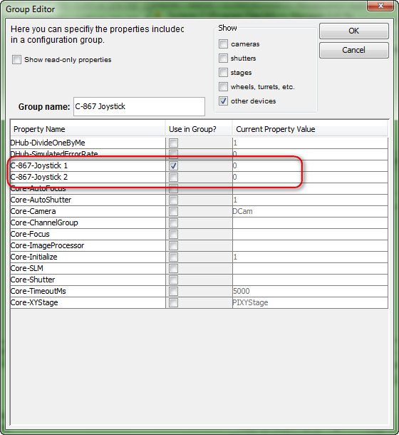
Joystick Configuration
When the joystick is used the controller will not accept motion commands from the software. To switch joystick control on and off, create a configuration group, select “other devices” in the “Show” field, and select the “Joystick 1” or “Joystick 2” property of the controller. Afterwards you can activate the joystick by entering “1” and deactivating the joystick by entering “0” in the corresponding GUI element.
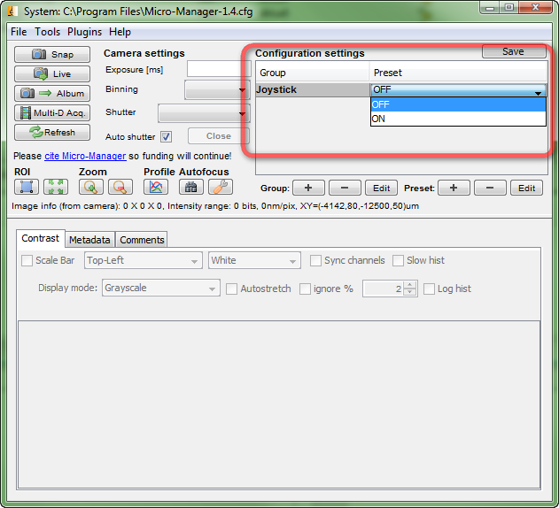
With presets defined a dropdown box can be created which allows activating (ON) / deactivating (OFF) the joystick with a simple action by the user:
To use a joystick that is not activated in the standard configuration of the controller, please use the “JAX” command to reconfigure the joystick according to the desired values and repeat the steps described above. Some controllers do not store this configuration to non-volatile memory. Here a custom startup controller macro can send the necessary “JAX” commands on each controller start.
For example: C-867.262 controller with USB joystick: To enable USB controller joystick, the joystick has to be reconfigured using the “JAX” command. The USB joystick is identified as number “3”. Use “JAX 3 1 1” and “JAX 3 2 2” to control stage axis 1 with joystick 3 axis 1 and stage axis 2 with joystick 3 axis 2. Since all changes will be lost when rebooting the controller, this procedure can be automated using an auto start macro in PIMikroMove:

Stage Axis Configuration
If the PI controller can activate HID control for single axes of the stages, the controller device will not have the “joystick” property, but all stages will show a new property “HID active”. If this is set to “1” this stage is controlled by the HID connected to the PI controller. The controller will not accept motion commands from the software for these axes. Setting it to “0” will disable the HID control and enable software commands.
Additional Axis Properties
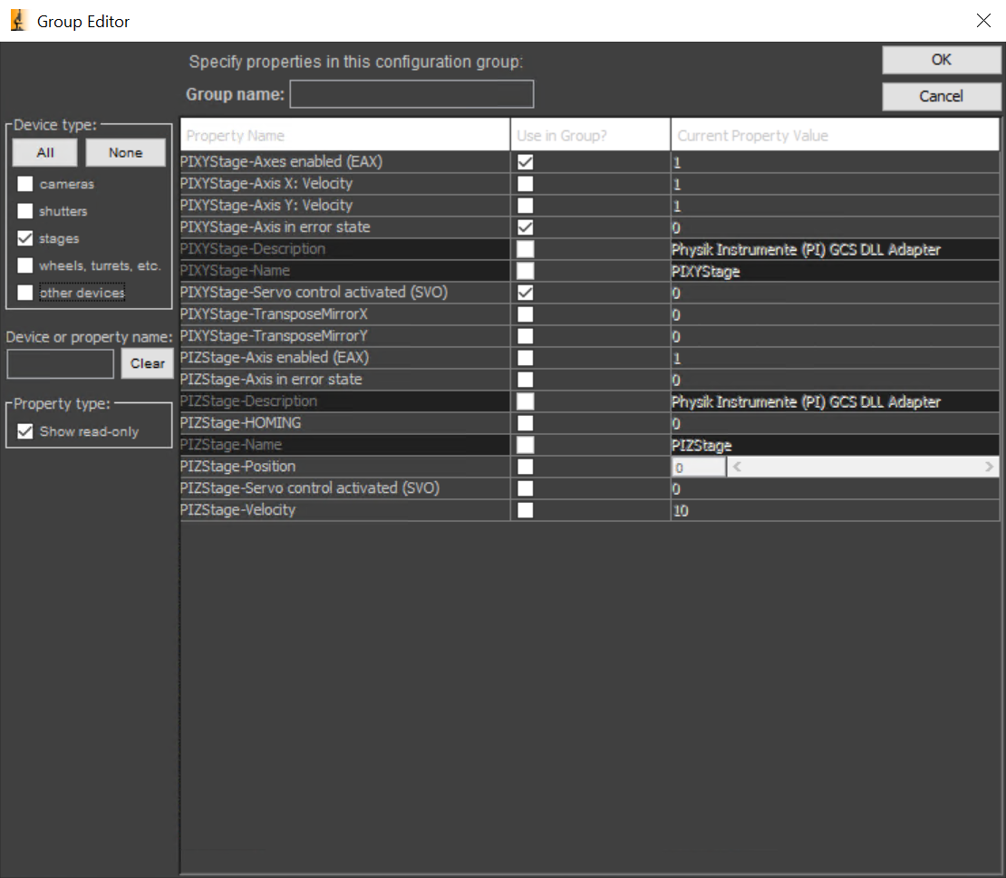
Servo control activated (SVO)
This flag can be used to activate (1) or deactivate (0) servo control for a PI stage.
Axes enabled (EAX)
This flag can be used to enable or disable the axes for a PI stage. In fact, the motors of the axes are switched on (1) or off (0).
Axis in error state
Under certain conditions a stage can enter an error state. When this happens, the property “Axis in error state” will be set to 1. To reset the error state, change this value back to 0. The value cannot be set to 1 manually.