Adapter for National Instruments DAQ with analog and digital outputs
|
Summary: |
Controls NI I/O boards through NI-DAQmx interface. Supports simultaneous hardware sequencing using multiple analog and digital output ports. Based on the NIMultiAnalog adapter. Replaces both the NIMultiAnalog and NI100x adpaters. |
|
Author: |
Nico Stuurman, Altos Labs. Based on NIMultiAnalog code by Mark Tsuchida, Open Imaging, Inc. |
|
License: |
LGPL |
|
Platforms: |
Windows only |
Replaces: NI100X and NIMultiAnalog.
This adapter provides digital and analog signal control for National Instruments cards.
The version of the NI-DAQmx library used to build this adapter is 9.2.
Most (or all) of the newer NI boards should be compatible. NI software (drivers) must be installed.
LabView is not required. This adapter supports hardware triggering of analog and digital output transitions,
as well as blanking of digital outputs. However, it does so through
different mechanisms, and uses capabilities that are not present on all
NIDAQ equipment. Digital output sequencing (and blanking) uses a feature
named ChangeDetection. A list of NIDAQ devics that support ChangeDetection
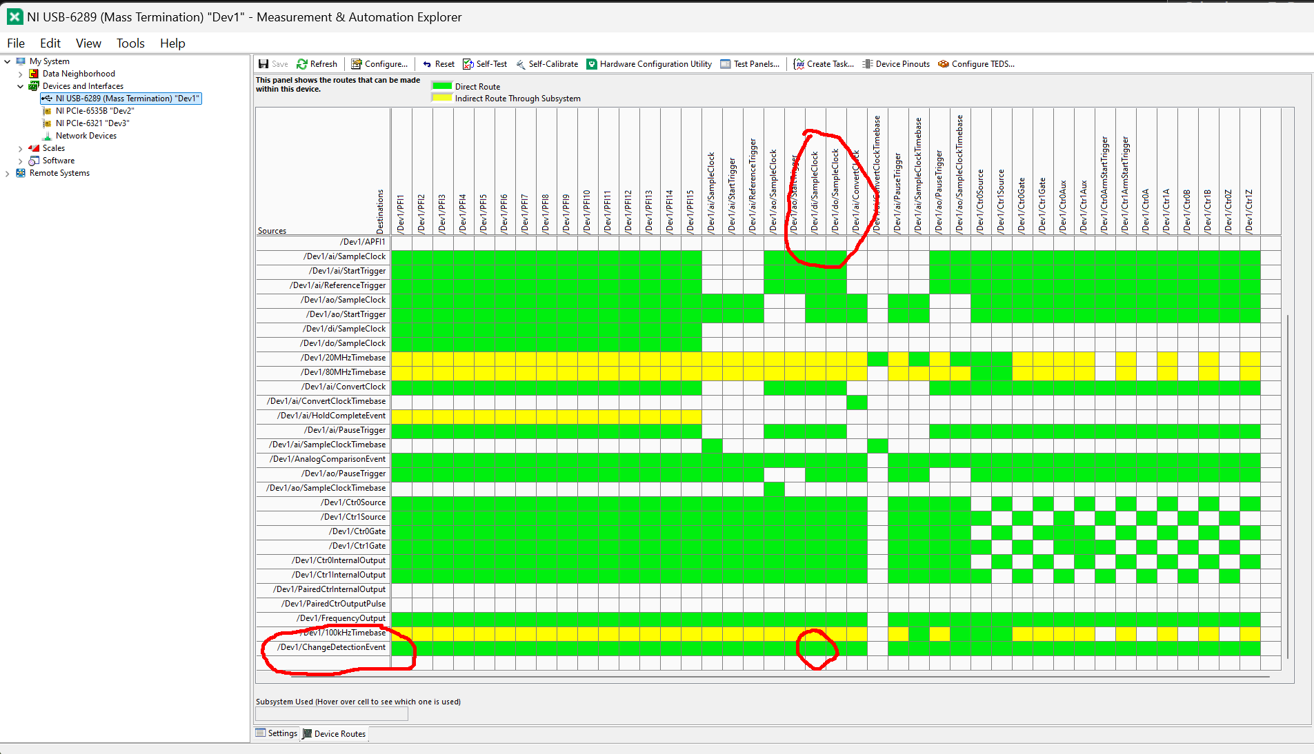
can be found here. In addition, the card needs to have internal wiring of the CHangeDetectionEvent to the di/SampleClock. Instructions how to check if a card supports this (preferably before you purchase) are below.
Configuration
To use this adapter, select the NIDAQHub device in the Hardware Configuration Wizard.
Select the Device name from the list (usually Dev1). You can set these names using the NI MAX application.
Note that if you change a device name in NI MAX, you will need to change it here as well.
Also note that you can generate virtual (emulated) devices in NI MAX (right click on
Devices and interfaces and select Create New...). The Max SequenceLength parameter
determines the maximum length of an analog or digitalsequence. The default (1024) is
likely high enough, but you can always come back here to increase it if needed.
The Hub device will detect which analog and digital ports are available in your device.
Select the ones you would like to use. The analog port lets you set the minimum and
maximum voltage that will be available within Micro-Manager (check the requirements
of the device you are driving with this analog output port). For Sequencing, you will
likely want the Use hub setting option, which lets you switch sequencing on and off
as a Hub-device parameter. The digital output port allows you to set the number of TTL
sliders. Set this to the number of pins you actually have connected. Start your
connections at pin 0 rather than some random number. This number should never be
more than the number of pins in your port. Setting it too high will clutter the
Device/Property Browser.
Triggering considerations
To use ChangeDetection (see above), the input pin needs to be part of the port that it controls. Therefore, if a port supports ChangeDetection, this Micro-Manager device adapter reserves the last pin of that port (i.e. p0.7 for the first 8 pin port of a given Dev) for input. You can change the pin used as the trigger source (it is a pre-initialization property of the device), but you can not use any pins above the input pin for output. To hardware trigger an analog output port, however, the input pin needs to be one of the PFI pins (selectable in the hub device). Therefore, if you want to control both analog and digital outputs with the same input trigger, you will need to physicall connect these two pins (for instance, run a wire between p0.7 and PFI0).
The hardware triggering support is flexible enough that you can use the same DAQ to control a piezo Z stage, the illumination channel (either using analog output ports as TTL outputs, with the DATTLStateDevice available in Utilities, or directly with digital output ports), and illumination intensities simultaneously. In such a configuration, both the Z stage and the illumination channel can be sequenced by hardware triggering at the same time in an MDA.
Digital output properties
The most important property of the digital output port is its State.
Each bit corresponds to one of the output lines of the
selected port (up to the limit of the number of lines in the port).
For example, if you have an 8-bit port, then the values of 0 through 255
(2^8 - 1) are valid. Setting State to 1 will turn on the first
line; setting it to 2 will turn on the second line; setting it to 3
will turn on the first two lines together; et cetera. To make it easier
to set the state, you can use the “TTL-#” properties. These control each
line (TTL/pin) individually. For instance, switching TTL-3 to 1 will result
in State 4, and will set the third line (probably called p0.2) high and all
other lines low.
Blanking will cause the digital outputs to only switch on when the TriggerInputPin
has the desired state. Usually you can leave Blank on set to Low, so that the
output will be active when the TriggerInputPin is high and low otherwise.
Since the digital output port is a state device, you can also use the
Utilities > State Device Shutter to create a shutter that can switch
the port on and off.
Check if a card supports ChangeDetection and if ChangeDetection is internally wired to the SampleClock.
Download and install the NIDAQmx software. This will include an application called “NI MAX”.
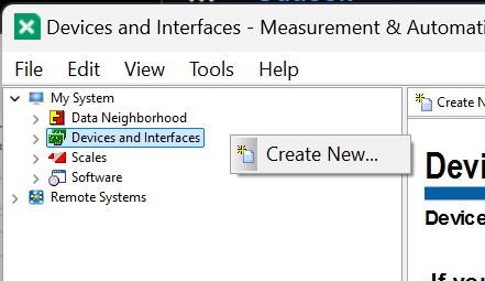
Start “NI MAX”. Right click on “Device and Interface” (open “My System” first if you do not see it), and select “Create New”.
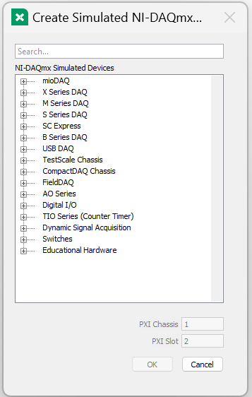
Select the card that you are interested in.
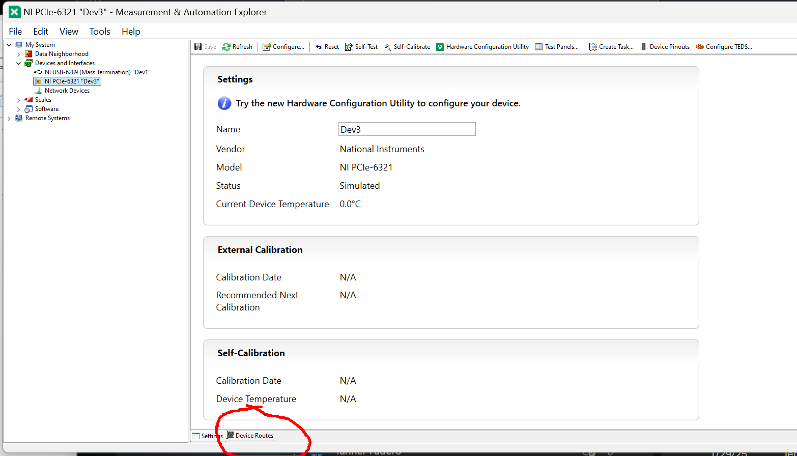
Under “Devices and interfaces”, select the newly created (virtual) device. In the bottom of the right pane, click on “Device Routse”.
Now look for the intersection of Dev/DI/ChangeDetectionEvent and Dev/DI/SampleClock. If the intersection is white, this means there is no internal wiring between the two, and Micro-Manager can not use this card to synchronize digital output with digital input.
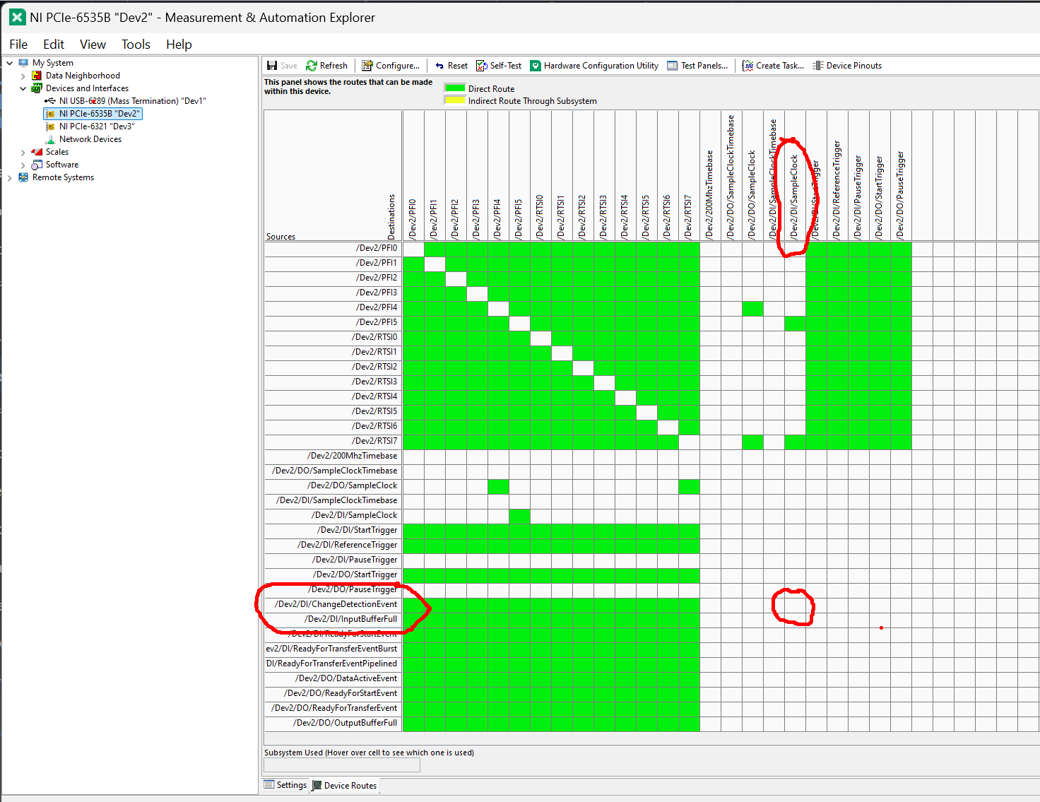
If the intersection is green, you are good to go.
