Micro-Magellan is a plugin for imaging large samples that span multiple fields of view (e.g. tissue sections, whole slides, multi-well plates). It provides a graphical user interface for navigating around samples in X,Y, and Z called “explore acquisitions”, as well as features for defining and imaging arbitrarily shaped regions of interest (“Surfaces” and “grids”).
Micro-Magellan is integrated with Pycro-manager, so all of its features can be controlled programmatically through Python, creating the possibility of powerful hybrid GUI-code applications, such as manually controlling data acquisition through the while having custom Python code processing image data on-the-fly.
A high level overview of the capabilities of (an older version of) Micro-Magellan can be found here
Up to date source code can be found here
Note: The materials in this documentation correspond to an older version of Micro-Magellan. Although all the functionality is the same, many GUI components have moved around (i.e. buttons are in different locations than in the screen schots).
Getting Started with Micro-Magellan
Download and install the latest nightly build of Micro-Manager (at the time of this writing that would be Micro-Manager 2.0gamma).
Open Micro-Magellan from the “Plugins–Acquisition Tools” menu in Micro-Manager.
In order for Micro-Magellan to operate, it needs to know the direction of Z movement (if your system is equipped with a motorized z drive). This is defined in the Hardware Configuration Wizard.

In order for Micro-Magellan to acquire tiled images and assemble them, it must have an accurate pixel size calibration for the objective in use. This can be done using the micro-manager pixel size calibrator tool, which can be found under Devices-Pixel size calibrator.
Memory settings
Make sure sufficient memory is allocated (important for making large surfaces in Magellan): Select the ImageJ toolbar select “Edit–Options–Memory and Threads”. 2048 MB is recommended and 4096 is even better for systems that can support it. If this number is changed you will need to restart Micro-Manager for it to take effect
Explore Acquisitions
Before exploring your sample you will need to enter your desired Z-step size and tile overlap. The channel group drop down is analogous to the channel group drop down within MicroManager’s Multi-Dimensional Acquisition and will be pre-populated with the configurations groups you have created. Select the settings group that contains your channel configurations.

Pressing “Explore!” will open a new window:

On the left side is your image area; a field of view will highlight blue as you hover over it. On the right, are look-up tables (LUTs) for each channel and several other acquisition setup parameters. To acquire an image in that area click to select (area will highlight green during active selection), once your selection is highlighted magenta, click again to confirm. You can click and drag to select multiple fields of view to be imaged. The “Z limits” scroll bars below the image window control which Z locations will be imaged, and will adjust automatically to the selected Z-step size.

Once you have begun to image, the Z-plane currently being displayed will appear dark green in the Z-limits scroll bars. Other acquired Z-planes will appear light green. In the example above, a Z-stack has already been collected (light green), and additional Z-planes will be collected between the new Z-limits.
You can review acquired images by scrolling with the “Z” bar, and right-clicking and dragging to navigate in the XY plane. You can also zoom in and out by using the mouse scroll wheel with the image window selected.
Once you have explored your sample and would like to select areas to image over time, with more optimized parameters, better Z-resolution, etc. you can use either the “Grids” or “Surfaces” tab above the LUTs to do so.
Grids
In the Grids tab, you can define an N x N grid, which will appear over your explored image. With the Grids tab active, you can drag this grid over the area you would like to image. You may generate multiple grids of different sizes by pressing “New Grid”, and then move them to different areas.


All of the grids generated in explore mode will populate the “grids” tab at the top of the Micro-Magellan main window, next to the Device status/control tab. If you are creating multiple grids, it may be helpful to toggle back to the Micro-Magellan main window, and select and rename the grids with their identifying features (ie: airway, duct, tumor).
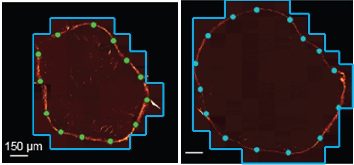
Surfaces
The surfaces tab allows you to create and edit surfaces, which can be used to define non-rectangular acquisition volumes or automatically vary hardware settings based on sample morphology during acquisition. Surfaces are created by marking interpolation points on 2D slices of an image. Micro-Magellan then uses these points to interpolate a continuous surface.
A new surface can be created by clicking on the “New Surface” button. Left clicking on the image screen with an active surface adds points. Right clicking on a point will remove it.

The Z-slider is then moved down further into the sample to specify an additional 2D slice of interpolation points.

The following video shows how to use an explore acquisition to explore cells on a slide that is tilted relative to Z axis, find the correct focal plane at 3 different points, and create a surface that passes through these three points:
Acquisition
All of the grids and surfaces generated in Explore mode will populate the “grids” and “surfaces” tabs at the top of the Micro-Magellan main window, next to the Device status/control tab.

Below the Explore mode settings, there are a series of tabs to manage acquisition setup.
Saving
The “Save” tab allows you to define the name of the acquisition and uses the same directory as the explore mode. To set up a simple single area acquisition, enter a name fore the file.
Time
In the “Time” tab, you can enter a time interval between image acquisition and the total number of time points to acquire

Space
In the “Space” tab there are several options for defining the volume you want to image. In a simple Z-stack you enter start and end Z positions, and either the grid or surface to define XY location and positions. If you have created surfaces, you can also elect to image the area between two defined surfaces with a buffer on either side.
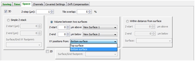
XY footprints can be either grids or surfaces, and define the XY positions that are used for a given acquisition.
The Z slices that are collected for a given acquisition can be defined in several ways:
Simple Z Stack
The same Z-slices are imaged at every XY position, creating a tiled cuboidal volume
Volume between two surfaces
Supply two surfaces to bound the top and bottom slices to collect at each Z stack. This is useful for defining 3D imaging volumes with complex shapes.
Within distance from Surface
Z slices are collected within a given distance above a below a surface. This is useful, for example, for collection a given distance from the top of a tissue, or for imaging a rectangular region that is tilted relative to the optical axis.
Channels
The “Channels” tab allows you select which of the available channels to collect, and the exposure time for each.
Setting Up Multiple Acquisitions
To acquire more than a single grid or surface at a time, select the “Setup multiple acquisitions” tab. Click “+”, this will add a line with the name currently entered in the “Saving” tab below. Enter the parameters for this acquisition in the other acquisition settings tabs.

Clicking “+” again will add another line, it will appear with the same name. Highlight the second (new) acquisition and change its name in the “Saving” tab below, and change necessary parameters in the other acquisition settings tabs. “Run all” will sequentially complete all acquisitions listed.
If you would would like to collect time lapse data in different areas in parallel (rather than completing a time lapse in one area, and then beginning the second time lapse in another area), select “In parallel” and then “Run all”

Changing settings during acquisitions
To accommodate the dynamic and often unpredictable nature of biological specimens, Micro-Magellan supports the changing of acquisition parameters while the acquisition is in progress. This includes all settings on the “Acquisition Settings” GUI, with the exception of “Z-step size” and “tile overlap %.” Often, users may want to pause acquisition while doing so, though this is not required.
Changing settings in this way allow acquisitions to be expanded in the Z direction beyond their original bounding boxes. The XY positions can also be changed during acquisition by swapping or modifying XY footprints. However, all XY positions imaged at any point during the acquisition must be present in its footprint at the start. Positions can be removed by changing the footprint and later re-added, but new positions cannot be created during acquisition to expand the imaged area beyond its original XY bounds. Practically, this means if imaging a sample that is expected to move or change over the acquisition, it is a good idea to use an XY footprint containing all possible XY positions where the sample might be imaged. If only a subset of the positions need to be imaged at the initial time point, the acquisition can be immediately paused after starting, and the XY footprint adjusted to a smaller area
Data Analysis
In addition to its open file format specification, there are specific mechanisms for importing μMagellan data into common software packages for visualization and analysis of 3D imaging data.
Micro-Magellan and Imaris
The Imaris-μMagellan compiler is a FIJI plugin for stitching of Micro-Magellan datasets and conversion to the IMS format. To use: 1) Download and install the plugin using the instructions at the following link: http://biomicroscopy.ucsf.edu/mediawiki/index.php?title=Analysis_Software_Repository#Imaris_MicroMagellan_Compiler 2) Open ImaricμMpiler from FIJI’s plugins menu 3) Drag the root directory of a μMagellan dataset onto the ImaricμMpiler GUI to import it. Stitching settings will automatically be imported from the overlap specified at acquisition time in μMagellan 4) Press start
Micro-Magellan source code
Current source code can be found here
Citing Micro-Magellan
If Micro-Magellan is useful to your work, please cite this article.
Authors: Henry Pinkard, Kaitlin Corbin
Available since version: 1.4.22