Micro-Manager User’s Guide
Nenad Amodaj, April 2006
Updated for version 1.0.54 (beta) on December 4, 2006
Updated for version 1.0.61, on January 31
Updated for version 1.2.35 on August 23, 2008
Updated for version 1.3.22 (beta) on February 11, 2009
This user guide was updated on July 24, 2009 (version 1.3.40).
‘’’
Introduction
Imaging cells has become an essential technology in many laboratories working in the life sciences. The components needed for such image acquisition consist of a microscope, cameras, light sources, mirrors, filters mounted in motorized filter wheels, x-y-z stages, and shutters. In practice, many complicated sequences of motorized operations are needed to achieve the imaging strategy desired by the researcher (e.g. acquiring images from multiple wavelengths). Thus, computer control of image acquisition is an integral part of contemporary microscopy.
From the user’s standpoint the whole setup (a microscope equipped with camera, stage, filter wheels, etc.) should ideally appear as an integrated, coherent system – an “appliance.” This appliance should allow for effective and comfortable interactive work, as well as unattended, completely automated operation.
Available commercial packages more or less provide the needed functionality for controlling automated microscopes, but, because they are proprietary and closed, they are difficult to extend and customize. New devices cannot be added to the system unless the software vendor chooses to provide appropriate drivers. Sometimes the cost of configuring the system with all necessary software and drivers can be quite high.
In contrast to virtually all of the available commercial solutions, Micro-Manager supports multiple platforms (Windows, Mac and Linux) and provides an open plugin interface for adding new devices. In addition, Micro-Manager is compatible with the widely used image processing package ImageJ, which is also available in the public domain. Combined with ImageJ, Micro-Manager provides a full-featured microscope management and image processing package, comparable in capabilities to commercial solutions. It is distributed free of charge and under an Open Source license. Its code base and functionality can be customized, extended and re-used with practically no restrictions.
Installation
After you install Micro-Manager according to the instructions for your platform (below), you can test-drive the software in demo-mode. The application will start in demo-mode by default after initial installation. To use Micro-Manager with your microscope you will need to create a configuration file for the specific hardware components that are part of your setup.
The configuration process is described in the Configuration Guide. Micro-Manager includes a number of sample hardware configuration files (with extension *.cfg); you will need to create a configuration file specific to your system, however.
Installation on Windows
Run the installer (MM_Setup_1_x_yy.exe) and follow the prompts. The package includes a copy of ImageJ; it may be necessary to install or update Java on your computer. Besides the manufacturer’s low-level drivers for your camera and possibly other equipment, no other software is required to fully use Micro-Manager. Micro-Manager will be installed in C:\Program Files\Micro-Manager1.y.
There are no particular hardware or software requirements. However, for practical use we recommend Windows XP, 1.7 GHz or better processor and at least 512 MB of RAM. Micro-Manager has been reported to work with Windows Vista.
Installation on Mac OS X
Double click on the file Micro-Manager_Mac(Intel/PPC)_1_x_yy.dmg. This will open a drive called ‘Micro-Manager_Mac(Intel/PPC)’. The drive is on the desktop and in every Finder Window. Open the drive (by double-clicking). In the drive there is a folder called Micro-Manager1.y. You can install the application by dragging this folder to your Applications folder, or you can launch the application by opening the folder and double clicking the ‘MM_ImageJ’ icon.
If you already use ImageJ
Micro-Manager is packaged as an ImageJ plug-in and contains a copy of the entire ImageJ application, together with the Java run-time environment. Starting Micro-Manager will automatically start ImageJ as well. If you already use ImageJ and have it installed on your machine, the original installation will not be affected. Micro-Manager installs and uses its own copy of ImageJ. However, if you have any existing ImageJ macros or plugins that you want to use with Micro-Manager, you will have to copy them manually to the appropriate sub-folders within the Micro-Manager folder. Migrating your favorite ImageJ plugins to Micro-Manager installation should not cause any problems.
Memory issues with Java/ImageJ
The Micro-Manager installation includes ImageJ and automatically runs ImageJ on startup. The amount of memory available to Micro-Manager is the same amount ImageJ allocates in the Java Virtual Machine, i.e. the available memory is determined by ImageJ. By default ImageJ is very conservative in allocating RAM: usually it reserves only 256MB of RAM, depending on the system configuration . This can be a problem when acquiring large time-lapse or z-stack sequences. In such situations Micro-Manager interrupts acquisition and warns you that it ran out of memory.
To increase the amount of memory available to ImageJ and Micro-Manager, use the ImageJ command Edit | Options | Memory. You should enter the amount of RAM equal or less to the amount you have installed on your system. (For systems with more than 1.2 GB of RAM, we have noticed that entering values larger than 1.2 GB can cause erratic behavior on some systems.)
If you have another installation of ImageJ on your computer, keep in mind that Micro-Manager installs its own copy of ImageJ and that you need to set memory options on both.
Getting started
On startup Micro-Manager displays a splash screen that allows you to choose a particular hardware configuration file. If you click OK without changing anything, the last successfully used configuration file will be loaded. The Demo configuration (software simulator) will appear as default the first time you start the application. This configuration can be used to explore Micro-Manager features, train novice users and as a reference point for troubleshooting.
Configuring Micro-Manager to work with your specific microscope setup is a complex topic, covered in detail in Configuration Guide. To make configuration easier, Micro-Manager includes the Configuration Wizard utility (Tools | Configuration Wizard) which provides step-by-step workflow for creating and managing your hardware configuration. However, we recommend that you try out the Demo configuration for a while before attempting to set-up and control a real microscope. All examples in this guide refer to the Demo configuration.
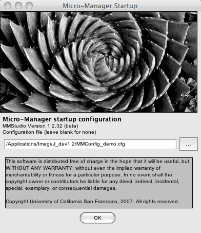
Figure 1. Startup screen: selection of the configuration file
You can also choose to skip loading a configuration file (delete the contents of the line in the Splash screen) in which case the application starts without any devices attached. Devices can then be loaded “manually” at any time using the Micro-Manager scripting features (see the Scripting section of the Micro-Manager wiki). A configuration file can also be loaded at any time using the menu command Tools | Load Configuration.
The Micro-Manager main control panel
Starting Micro-Manager will also start ImageJ (in fact, ImageJ starts up first and runs Micro-Manager as a plugin). Both ImageJ and Micro-Manager have their own menus (on the Mac you will need to click on either window to display the menu in the main menu bar). Unless specified differently, menu commands in this manual will refer to the Micro-Manager menu. The Micro-Manager and ImageJ windows appear differently on different computer systems; examples from multiple systems are used in this manual.
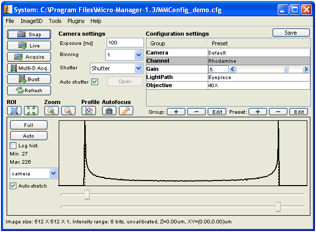
Figure 2. Main control panel displaying device controls and image
histogram
After the configuration file is loaded, the main control panel displays the current settings and shows the status of selected devices.
Snapping single images
To obtain a single image from the camera, press the “Snap” button. A “Live” window will pop up, displaying the acquired still image. You can use any of the available ImageJ tools to analyze, save or edit the image. In addition, at the bottom of the window there are shortcut buttons to save the image.
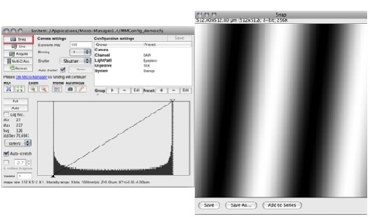
Figure 3. “Live” window.
Each time you press the Snap button, the image in the “Live” window will be updated. The Demo camera driver generates a spatial sine wave that shifts each time you snap a new image. You can also change any of the settings in the control panel and the changes will be immediate. The bottom part of the control panel displays a histogram of the image.
Live image mode
To see a continuously updated, “live” view from the camera, press the “Live” button. The images will be displayed in the “Live” window. Pressing this button again, stops live mode. Settings in the control panel can be changed during live mode and the effects on images in the “Live” window will be immediate.
Acquiring a series of images
With the “Acquire” button, you can collect a series of still images (snaps) in an image series window. The first time you click the “Acquire” button, a new series window will open, with a fresh image obtained from the camera. Every time you click the “Acquire” button thereafter, a new image will be added to the series. Buttons that “Snap a new image and overwrite” and “Snap and append” are also available in the series window. Click the “Save” button to write all images in the series window to disk.
Histogram, brightness and contrast
A histogram of the current (“Live” window) image’s pixel intensities is alway displayed in the graph in the lower part of the main panel. The histogram is automatically updated each time a new image is received. The histogram intensity range can be adjusted, by selecting “camera”, “8bit”, “10bit”, “12bit”, “14bit”, or “16bit” scale. Selecting the “camera” setting will automatically adjust the histogram range to the hardware bit depth of the image.
Brightness and contrast of the image display can be adjusted by moving sliders at the bottom of the main panel, under the intensity histogram. By controlling the lower and upper clipping levels, you are changing the brightness and contrast of the displayed image. The “Auto-stretch” option will adjust minimum and maximum settings automatically, based on the extreme pixel values in the image. Any settings will apply only to the image display - the actual pixel values will not be affected. Since Micro-Manager displays images received from the camera in a standard image window, any ImageJ command can be used to adjust the appearance of the image, including the standard ImageJ Brightness and Contrast dialog.
Refresh
The Micro-Manager main panel will not necessarily be updated when a setting in your microscope changes. This behavior saves resources and avoids continuous polling of the hardware. To bring Micro-Manager in sync with the current state of the hardware, use the ‘Refresh’ button.
Region of Interest (ROI)
Most of the cameras used for microscopy can be configured to image only a Region of Interest (ROI) instead of the full frame. To select an ROI use the rectangle tool (from the ImageJ window) on the image window. By pressing the “ROI” button while the selection is active, you will apply the current rectangle to the camera. Some cameras will internally adjust the rectangle dimensions slightly to fit within specific hardware constraints. To return to the full frame imaging, press the “Full” button (right next to the ROI button).
Zoom
The “Zoom” buttons apply a software zoom to the topmost image window.
Line profile
The “Profile” button opens up a live line profile window. Unlike the regular ImageJ “profile” utility, this window will update each time a new image is displayed in the Live window. The profile is computed from the currently active line drawn over the image. To draw a line profile a region, use standard line tool from the ImageJ toolbar.
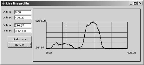
Figure 4. Line Profile window.
Camera Settings
A few settings found in all systems are directly accesible. You can set the exposure time of your camera, and apply binning (‘pooling’ of pixels in both x and y direction). Also, you can change the ‘active shutter’, i.e., the shutter that Micro-Manager will open before taking an image and close once the image is made. This behavior of automatically opening and closing the shutter can be defeated by unchecking the ‘Auto shutter’ checkbox. Doing so will let you open and close the active shutter with a button in the main control panel.
Controlling devices
Exploring devices: Device/Property Browser
The main control panel provides control only of a small subset of the device properties loaded in the system. To view and control all devices and all settings available in the currently loaded hardware configuration, use the “Device Browser” (menu command Tools | Device/Property Browser). The Device Browser displays a list of all devices and associated “properties” (settings available for each device). Since this list will often be overwhelmingly long, you can restrict the list of displayed devices using the checkboxes in the top left corner of the window. You can inspect and change any setting on any device. Read-only properties are shown as a line with a dark background. To change a setting, change it in the ‘Value’ column and then leave the field using the ‘tab’ key or by clicking the mouse elsewhere in the window.
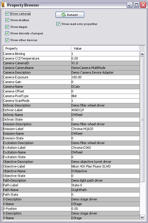
Figure 5. Device/Property Browser window.
Grouping device properties: Configuration Presets
Obviously, changing individual properties using the Device/Property Browser quickly becomes cumbersome. Micro-Manager therefore provides a way to generate ‘shortcuts’ that let you quickly set groups of device properties. Setting up these Configuration Presets is an important part of configuring Micro-Manager and is described in the Configuration Guide. Placing the cursor over the current preset will display a tool-tip window and show which devices will be affected by the command. In the example in the configuration guide, choosing the “DAPI” channel preset command will move three filter wheels to the appropriate positions.
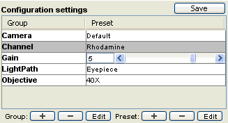
Figure 6. Detail of the main control window: configuration preset.
There is no limit to the number of devices or number of different properties you can include in one configuration group. You can set objectives, filters, stage positions, camera parameters in a single configuration command. The Configuration Presets shown here are just an example (used in the demo configuration). In some cases, device properties can show up as a slider, making it easy to set things like camera gain or temperature.
Recording Images
Multi-dimensional acquisition
To acquire multi-image stacks, press the “Multi-D Acq.” button to open
the Acquisition Control dialog (this dialog can also be reached through
the ’’’ Tools | Acquisition ‘’’ menu entry). Micro-Manager
allows you to create a stack as multi-channel (wavelength coordinate),
multi-frame (time coordinate), multi-slice (Z coordinate), or any
combination of the above. Such stacks will be referred to as “5D image”.
In addition, 5D Images can be acquired at multiple positions.
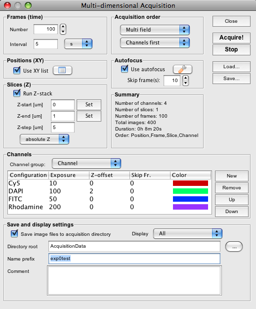
Figure 7. Acquisition control dialog.
After defining channels, slices and frames by using controls in the dialog, press the “Acquire” button. The acquisition starts immediately and an Image Viewer window will open displaying the progress. During and after acquisition you can use buttons at the bottom of the Image5D window to play-back the sequence, browse channels, slices or frames, display metadata or save the entire image stack to disk.
Channels can be selected from the active ‘Channel group’. Channel groups are the Configuration Preset groups that are defined in the main Micro-Manager control panel. When you switch Channel groups, all previously defined channels will be erased. You will need to set the desired exposure time for each channel. You can also set a z-offset for each channel, which can be useful when the main object in one of the channels is in a different focal plane from the other channels. Setting ‘Skip Frame’ to a number other than 0 will cause the acquisition to ‘skip’ taking an image in that channel (after taking the first image) for the indicated number of frames. The Image5D Viewer will ‘fill in’ these skipped frames with the previous image. In some situations it may be desirable to acquire certain channels at lower sampling rates, to reduce photo-toxicity and to save disk space. Clicking inside the ‘Color’ column will open up a Color selector that lets you select the color to be used for that channel in the Image5D Viewer. (You can also change colors later on in the Image Viewer.)
Z Slices can either be set as relative to the current position (you will need to type in the start and end position) or as absolute positions. Upon selecting absolute positions, the ‘Set’ buttons will become active. Clicking these will set the current position to start or end.
Acquisition Order lets you choose between carrying out z-stacks with each channel (Slices first) or switching channels at each z-position (Channels first). Multi field mode will take a complete 5D image set at a position before moving on to the next, wehereas Time lapse mode will taking images at each position for each time point, in effect acquiring time lapse sequences at all positions. To do so, acquisition in Time lapse mode will open Image5D viewers for each position
Checking the Use XY list option will cause the acquisition to be executed at each position defined in the Position List. Autofocus options are described below. In the acquisition dialog, if the Save files to acquisition directory option is selected, images will be saved to disk continuously during the acquisition. If this option is not selected, images are accumulated only in the Image5D window, and once the acquisition is finished, the image data can be saved to any location on the disk. However, saving files automatically during acquisition secures the acquired data against an unexpected computer failure or accidental closing of image window. When using ‘Multi field’ mode and autosaving, the Image5D Viewer for each position will be closed before the viewer for the next position opens, thus saving memory. Checking the Display only last frame option will only display the last acquired frame in the Image 5D viewer (all others can be found on disk).
Burst Mode (Fast Imaging)
Time lapse sequences can be acquired using the Multi-dimensional acquisition dialog. However, this causes the software to ‘snap’ images at each consecutive time point. Most cameras will not operate at their top speed in this mode, so if you would like to acquire fast ‘streams’ of images, you will need to use the Burst mode, which can be accessed by pressing the “Burst” button in the main control window.
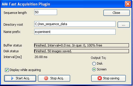
Figure 7. Burst Mode Acquisition dialog.
Set up the camera (exposure time, binning, etc..) in the main Micro-Manager window. Specifiy the number of images you would like to collect. The resulting sequence can either be saved to disk or displayed in the Image5D Viewer. When saving to disk it is possible to acquire sequences larger than the RAM available in your computer (provided that the images are saved to disk fast enough). Specify the ’ Directory Root’ and Name Prefix when saving to disk. Micro-Manager will automatically add consecutive numbers to the ‘Name Prefix’ when the name already exists, so you do not need to change the Name Prefix between acquisitions. Unchecking the Display during acquisition option can give a slight performance increase. The camera will report what interval between images it expects to achieve during acquisition.
The acquisition is performed asynchronously at the specified hardware speed, using an internal circular buffer to smooth out display and disk streaming lags. If disk streaming gets too far behind the actual acquisition rate, the buffer may overflow. The size of the internal buffer can be specified in the Tools | Options menu. Default size is relatively modest (25 MB) and can be increased to almost all available RAM. However, allocating large chunks of the available memory to the buffer may impair overall performance and limit the size of the time lapse sequences in other acquisition modes.
Split View
There are some devices on the market that can split an image into 2 (or more) wavelength components and project these side by side on a camera (examples are the Dual View and the OptoSplit). The SplitMode tool (under the Tools | Split View menu entry) will display the acquired images as a two channel Image in the Image5D viewer. You can set the color of each channel and use either a left-right or top-bottom split.
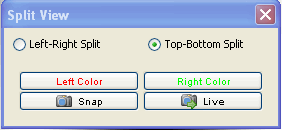
Figure 8. Split View dialog.
Autofocus
Micro-Manager has a single, integrated user interface for hardware- and software-based autofocus. In the main window, press the Set autofocus options button to open the Autofocus Properties dialog box. Here you can choose which autofocus mechanism to use among available hardware- and software-based options. You can then edit the settings for your chosen autofocus mechanism. The Duo autofocus option allows you to combine two autofocus mechanisms, so that they operate sequentially, one after the other.
The Autofocus Now button on the main window will cause the autofocus mechanism you have chosen to execute its focusing protocol once.
Hardware Autofocus
Hardware-based autofocus support is provided for the Nikon Perfect Focus (PFS), ASI CRIF, Zeiss Definite Focus, and Olympus Z Drift Correction (ZDC) devices. These devices bounce an infrared reference beam off a surface of the coverslip, and use this reflection to adjust the focal position. To activate one of these devices in Micro-Manager, you need to include it in the Hardware Configuration and select it in the Autofocus Properties dialog.
Software Autofocus
Software-based autofocus plugins are also available in the Autofocus Properties dialog. They should work with any camera and Z-stage. These autofocus plugins iteratively adjust the focal position and acquire images to optimize a specific image feature. For example, Pakpoom Subsoontorn & Hernan Garcia (Caltech) contributed a Java plugin module (“JAF H&P”) for auto-focusing based on the relative strength of gradients in the image (edge ‘sharpness’). See here for further documentation of this autofocus plugin.
Autofocus in Multi-D Acquisition
The Multi-Dimensional Acquisition window offers integration with the autofocus system. The Set autofocus options button allows you to choose the autofocus mechanism and configure it. Click the Use autofocus checkbox to activate autofocus in the multi-dimensional acquisition. You can also specify how many frames (time points) will be skipped between autofocus events.
Positioning
Position List Dialog
The Position List dialog can be reached from the menu (Tools | XY List), and from the Multi-dimensional Acquisition window (button next to ‘Use XY list’). The Position List is used to record the positions of stages in your system. At the bottom of the dialog is a list of available stage axes, any of which you can select to use for recording positions.
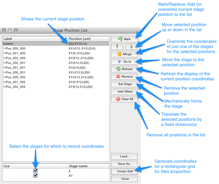
Figure 9. Position List dialog.
Use the Mark button to record the current stage position for all stages you have selected to use. When a position is selected (as shown in Figure 9) pressing the Mark button will overwrite the selected position. Positions can be de-selected by clicking on them. You can revisit a site by selecting the position and pressing the Go to button. The button will update the stage positions shown in the Current position pane. Position lists can be saved (Save As button) and re-used later (Load). When saving and re-using position lists, you should make sure that the coordinate systems of your stages are reproducible between invocations of the program, possibly using the calibrate button. This will drive all stages to their origin and set this as the base of their coordinate system. Be extremely careful when doing so, since it is possible to run your XY stage into one of your expensive objective lenses!
Tile Creator
The Create Grid button in the Position List Dialog will open the Tile Creator Dialog. The purpose of this dialog is to quickly create a position list covering the area of an object (larger than a single image) in the microscope specimen.
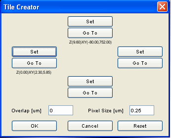
Figure 10. Tile Creator dialog.
Use the Set buttons of the Tile Creator Dialog to mark at least two of the corners of the object that you are interested in. Pressing OK will generate a Position List that covers a bounding box around the corners that you set. To do this correctly, the dialog needs to know the correct Pixel Size. If your system is calibrated, the correct pixel size will appear here automatically; otherwise you will have to enter the correct number. It is also possible to specify an overlap between the images generated from this position list (to specify a space between them, use a negative overlap).
Interactive Stage Movements
It can be cumbersome to exactly position a microscope stage. Micro-Manager has an option (Tools | Mouse Moves Stage) that might make this easier. To use this tools, your Micro-Manager configuration must be calibrated. When Mouse Moves Stage is enabled, double-clicking in the “Live” window (the window in which the “Snap” and “Live” buttons display images) will move the stage such that the place you double-clicked will move to the center. It is possible that the stage moves the wrong direction. If so, use the camera properties ‘TransposeMirrorX’, ‘TransposeMirrorY’, and ‘TransposeXY’ (accessible in the Device/Property browser) to achive the correct stage movement (you might want to save these settings in a ‘System-Startup’ configuration group). You can also move the stage by dragging the mouse through the image (a kind of ‘Google Earth’ effect).
When the “Live” window is open, you can also use the keyboard to move the stage:
Commands |
x,y modifiers |
z modifiers |
Image Viewer, Files and Metadata
Image5D Viewer
Micro-Manager uses an image viewer derived from Joachim Walter’s Image5D ImageJ plugin. The viewer has sliders for both the z and t dimensions, and can display channels as an overlay.
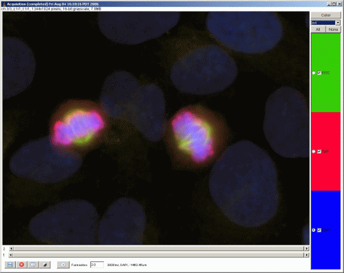
Figure 11. Acquisition data displayed in the 5D image window.
The button on the top left (Color) lets you set the color of the selected channel. The dropdown menu below lets you switch between gray (a single channel displayed in grayscale, switch between channels using the slider), color (similar, but the channel is displayed in color), and overlay (the default: an overlay of visible channels. Make channels visible/unvisible using the checkboxes, switch the ‘active’ channel using the radio buttons). Buttons on the bottom of the window (left to right): Save, Stop the currently running acquisition, Pause acquisition, display Metadata, open Brightness/Contrast tool to adjust the currently selected channel, start/stop Playback of the time series. Adjust the Playback speed using the text box (set in frames/second). The bottom bar will also display the time point at which the displayed image was taken, the channel and the z-depth.
Operations on Images
To load previously saved data and open a corresponding Image5D Viewer, use the File | Open Acquisition Data As Image5D menu command from the main control panel. Since Image5D is not a data structure native to ImageJ, some of the ImageJ commands will not work on these images as expected. To alleviate this problem, Micro-Manager brings a set of functions that can help working with Image5D images. These can be found under the Image5D menu entry in the main Micro-Manager window. Of special note is the Volumeviewer, which is Kai Uwe Barthel’s Image plugin modified to work directly on the selected Micro-Manager Image5D window.
Note that you do not need the full Micro-Manager installation to open the Micro-Manager Image5D data. Instead, you can install the Micro-Manager ImageJ Reader plugin that lets you open Micro-Manager files in an Image5D viewer and lets execute a number of operations on these images.
Metadata
The Metadata button at the bottom of the Image5D viewer will bring up a window displaying all Metadata. Initially, the window shows the Comment tab. This will contain the comments you typed in beforehand in the Comment field in the Multi-dimensional Acquisition window. You can make changes to the Comments here. Pressing the Save button will save your changes to the comments, along with changes you might have made to Brightness/Contrast of the image (pixel data will not be changed). The summary tab will display a summary of data common to the acquisition. The Image tab displays data sepcific to the frame (like the channel and time point it was taken). When changing frames, time points or channels in the Image5D viewer, data in the Image will be updated accordingly. The State tab contains all the complete state of your microscope system at the time the displayed image was taken.
Files on Disk
Micro-Manager will store a single Image5D dataset in a single folder. Acquired images are saved to disk as separate TIFF files, each containing a single grayscale image. The file naming convention is “img” prefix followed by frame number, channel name and slice number (img_00000000t_channel_00z.tif). In addition, the folder will contain a file named “metadata.txt” that contains the metadata in JSON format.
Credits, License and Copyright
Micro-Manager is an Open Source software package for controlling automated microscopes on multiple platforms (Windows, Mac and Linux). The software is being developed in the Vale Lab at the Unversity of California San Francisco and funding was provided by the Sandler Foundation and a grant from the NIH. The software is designed and developed by Nenad Amodaj with help from Nico Stuurman. The Micro-Manager source code is distributed under the BSD license for the user interface and the LGPL license for the MMCore (control module). All supplied device drivers (‘adpaters’) for cameras and other devices are covered by the BSD license. Copyright for some of the adapters is owned by other parties.
