The Nikon TI Eclipse is a fine motorized microscope, however, its designers forgot one little detail. The tube lens switcher can switch between a 1x and 1.5x tube lens but since it is not encoded there is no way for software controlling the microscope to know the magnification of the image. Of course, a diligent microscopist will take note of the position of that switch and it is even possible in Micro-Manager to add a “dummy” tube lens switcher, however, more often then not, you will end up in a situation where you are not certain whether you used the 1x or 1.5x tube lens, basically rendering a data set useless.
To remedy this problem, I started encoding the tube lens switcher myself. The three main components to do so are:
- Hall effect sensor. These are small devices that change output voltage depending on the presence of an electric field. This write-up is for the the A3214EUA-T (inscribed with EA1) from Allegro. It is no longer available. I am currently using the A1126LUA-T (also from Allegro). Although the ground and Vout should be switched for this model (according to the data sheet), things work much better if you do not (i.e. keep them as shown below).
- Magnet. You want a magnet that fits into the screw hole of the tube lens switcher. Buckeyballs (no longer available) and Neocubes do a great job at this. You need only one of them (hope they are still available)!
- An Arduino board. Most of the standard boards (including the Uno) will do fine. This will provide power to the Hall effect sensor, read out its state and signal this to the Micro-Manager software.
To put everything together, I also used:
- Four stranded telephone wire (from the RadioShack)
- Telephone wire crimp connectors (see picture below)
- Arduino-compatible jumper wires
- An Arduino enclosure
You can exchange these for anything else that works.
I connected the Hall effect sensor to the telehone wire using crimp
connectors: 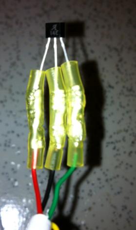
Then hooked up the telephone wire to the Arduino using the same crimp
connectors and M/M jumper wires. Note, the Hall effect sensor needs 5V
power (red wire) and ground (white/black cables), all provided by the
Arduino and its output (green wire) can be connected to the A0 pin on
the Arduino. I used a knot in the telephone wire to protect against
problems arising from cable pull. 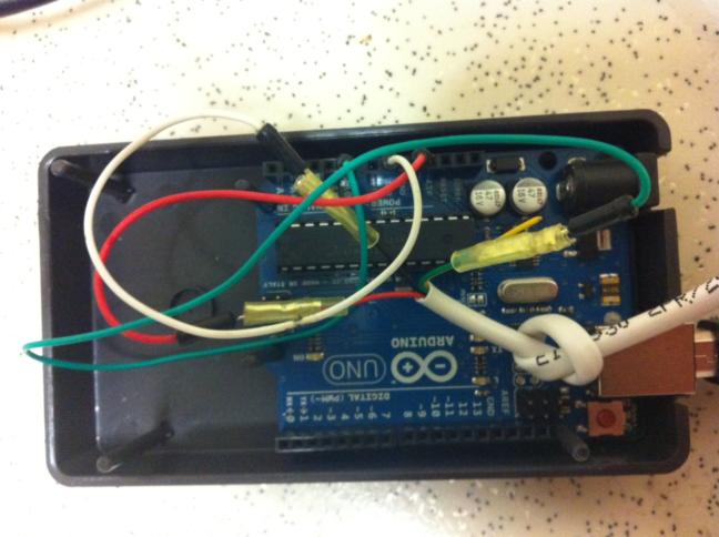
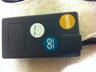
Close the box (you do not need to put the stickers on):
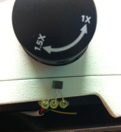
Now put the Buckeyball magnet in the screw hole in the tube lens changer
and position the Hall effect sensor right underneath. Fasten the sensor
using thick double sticky foam (put some souble sticky foam over the
sensor as well to make sure it does not break loose). Turning the know
will bring the magnet out of reach of the Hall effect sensor.
Load the AOTF firmware into the Arduino board. Configure Micro-Manager to use the Arduino-Input device. Set the pull up resistor property to “On”. You can either use just pin 0 or all pins. In the device property browser, you should see the value of this read-only input property change when the magnet is close to the hall effect sensor (the input updates automatically every second). Add this property to the pixel size configuration and Micro-Manager will always know the exact pixel size.