Overview of alignment process:
- Center laser excitation to objective back focal plane by tilting and positioning the scan head
- Focus camera on pinholes with transmitted light
- Position camera using uniformity slide
Laser Excitation Path Alignment
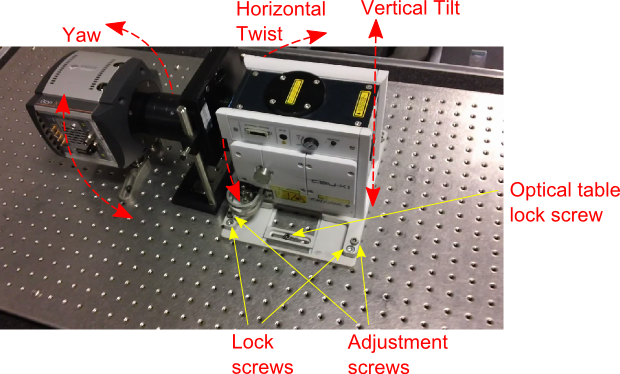
- Loosen the microscope C-mount adapter screws as below so that travel is available to align the Yokogawa head to the microscope optical axis
- The Andor Yokogawa tilt stage has 2 sets of 4 screws, each screw denoted with “A” (adjustment) and “L” (lock). Loosen all the Andor lock screws. Loosen the “front” Andor adjustment screws, i.e. the 2 adjustment screws closest to the microscope body. Now there are only 3 support points positioning the Yokogawa: the two “rear” adjustment screws and the C-mount port of the microscope. Using a spirit level adjust the “yaw” of the Yokogawa head to level with the microscope XY stage using the “rear” adjustment screws (“Yaw” is the horizontal axis front corresponding to the front-back of the microscope). This helps prevent clipping or vignetting later on. Now the Yokogawa now is mechanically level with the XY stage
- Align the Yokogawa to the microscope optical axis. Observe laser on the back focal plane of your fluorescent objective target. If the spot is to the left or right of the microscope, this indicates vertical tilt is off. Adjust the “rear” adjustment screws of the Andor tilt stage but adjusting both screws by equal amounts. If the spot is to the front of back of the microscope, this indicates horizontal twist is off. Physically twist the Yokogawa head on the optical table to one side and the other
- Now the laser will be centered on the objective back focal plane. Lock down the Andor tilt stage: lightly screw down the C-mount adapter lock screws as far as possible without disturbing the laser alignment. Start tightening the “front” Andor tilt stage screws barely finger tight. Engage all 4 Andor lock screws. Finally, tighten the optical table brackets of the tilt stage
Pinhole Focus
- Free the camera focus mechanism by loosening the M2.5 screws of the focus ring and the M2.5 screws of the outer camera flange
- Turn on the microscope transmitted light
- Turn off the key switch of the Yokogawa spinning disk so that pinholes are visible on the camera
- Move the camera toward and away from the Yokogawa head, and watch the value of the image maximum intensity. Noticing the change in focus is easier if the camera intensity counts are around the middle of the sensitivity range, so use gain if necessary
- After reaching the maximum intensity, lock only the focus ring (the camera flange screws will be locked after adjusting the “horizontal tilt” of the camera)

Emission Uniformity
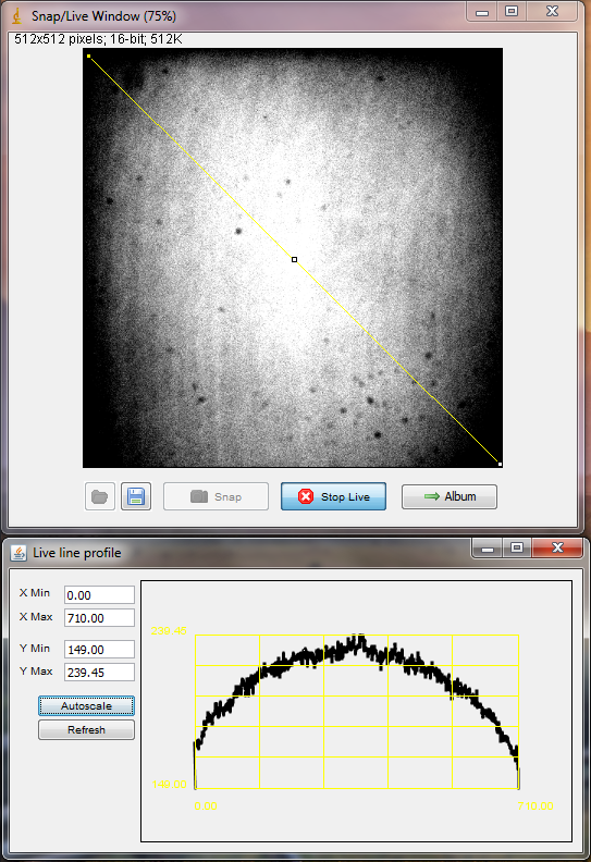
- Focus on a green uniform fluorescent slide (Chroma hands out a set of colored slides in a box for free at conferences). Green slide and 488 laser gives good emission (other colors of uniform slides produce insufficient emission intensity). The best way to know if you are really in focus is to watch the maximum intensity of the image, as with focusing the pinholes
- Use the Profile tool and draw a diagonal line across the image. Twist the camera horizontally, and adjust the camera feet height till the emission is centered on the sensor. Using a multi-colored lookup table helps see this, but since it’s broken in version 1.4.10 you can instead manually scale to see the corner drop-off and center of intensity
- Lock down the camera feet, filterwheel, and camera flange