Summary
Adapter for the ArduinoCounter device
| Author: | Nico Stuurman, Tanner Fadero |
| License: | LGPL |
| Platforms: | Linux, Mac, and Windows |
| Since version: | 2.0.1 |
| Wiki page Authors: | Tanner Fadero, Nico Stuurman |
Background
Hardware synchronization using TTL (Transistor-Transistor Logic) signals (aka “sequencing”) is a common technique used to significantly speed up hardware events in microscopy. In Micro-Manager, the most common way to sequence hardware is to use the camera as the “leader” and have a sequencing device (e.g. NIDAQ) “follow” the camera. The camera outputs TTL signals and the sequencing device listens to those signals and sends analog or digital signals to move or (de-)activate other devices, like a stage or a light source.
Using the camera as the leader is justifiable, cameras are usually the slowest device in a microscope, so every other device can wait for a signal coming from the camera before changing their states. Unfortunately, cameras don’t know how to count.
During a multi-dimensional acquisition, Micro-Manager will upload the sequence of events to the sequencing device and then send a serial command to the camera to begin running in “free mode” (acquire and send images as fast as possible). Once Micro-Manager receives the expected number of images, Micro-Manager sends a “stop” command to the camera. So, even if you ask Micro-Manager for a timelapse with n images, the camera will often acquire > n images before the camera receives the stop command. The exact number of extra images that the camera acquires varies based on speed of serial communication and exposure time, but in our experience, it’s rarely zero.
Cameras’ inability to count poses a problem for sequencing devices (which also can’t easily count)– they will advance the sequence at the camera’s TTL signal. This means that light sources will turn on and stages will move, even though the computer is not receiving images.
One solution to this problem is to put a counting device between the camera and the sequencing devices: the ArduinoCounter. The ArduinoCounter is a “fake” camera that passes TTL signals from the camera along to the sequencing device as long as the number of TTL signals is less than or equal to the expected number of images in a Multi-Dimensional Acquisition.
Hardware
We recommend obtaining the following pieces of hardware:
- 1 x Teensy® 4.0 Development Board (other Arduino IDE-compatible boards may also work) WARNING: Teensy boards are NOT 5V tolerant, so be sure that your camera TTL does not exceed 3.3V!
- 1 x USB 5-pin Micro-B cable
- 1 x BNCB1 BNC Bracket, Terminating
- 4 x M4x0.7, 10 mm long bolts
- 4 x M4 washers
- 1 x M6 or ¼-20” bolt (threading and length depending on your optical table)
- Low-voltage wire
- Solder with rosin core
- Soldering iron
- 3D printer
And to 3D print the following parts for the enclosure:
The holes in the bottom of the holder can be tapped with an M4x0.7 threaded tap.
Assembly
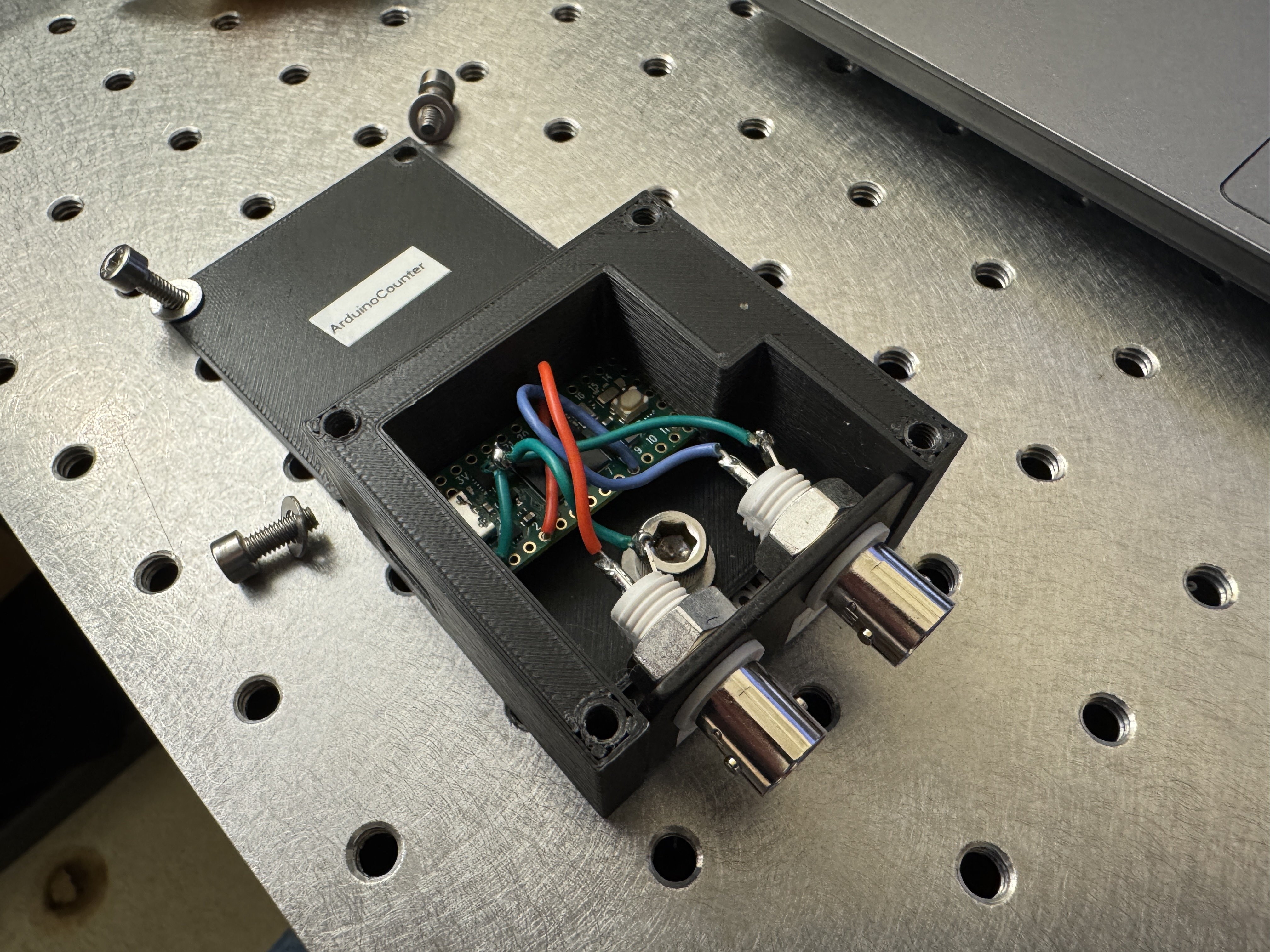
1. Connect the two BNC ground pins from the BNCB1 bracket by soldering a wire
between the two pins.

2. Connect the two ground pins from the BNCB1 bracket to the GND (ground) pin
of the Teensy 4.0 board by soldering a wire from either BNC ground pin to the
Teensy 4.0 GND pin.

3. Connect pin 2 on the Teensy 4.0 to the positive pin on the left BNC connector
on BNCB1 by soldering a wire between the two pins.

4. Connect pin 4 on the Teensy 4.0 to the positive pin on the right BNC connector
on BNCB1 by soldering a wire between the two pins. This is the “IN” pin, which
will receive a TTL from your camera.

5. Insert the Teensy 4.0 board gently into the 3D printed enclosure. Fold up any
excess wiring inside the enclosure. This is the “OUT” pin, which will send a TTL
to your sequencing devices.

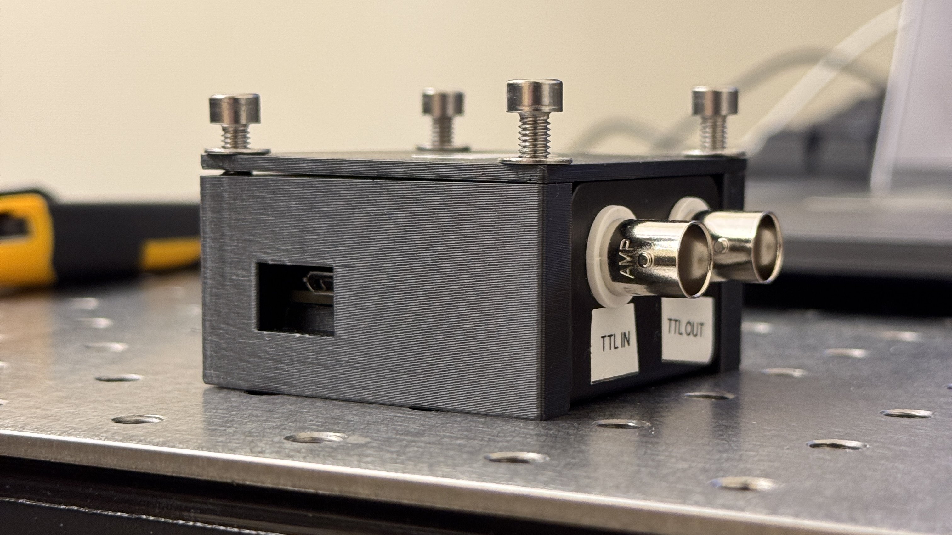
6. Insert the BNCB1 into the front of the 3D printed enclosure.

7. Attach the bottom of the 3D printed enclosure to your optical table with an
M6 or ¼-20” bolt.

8. Attach the top of the enclosure with 4 x M4x0.7, 10 mm long bolts and
4 x M4 washers.

10. Insert the micro-USB cable into your Teensy 4.0 and connect it to your CPU.

11. Connect the TTL out from your camera into the “IN” pin on your BNCB1 bracket.

12. Connect the “OUT” pin from your BNCB1 bracket into your sequencing device.


Software Configuration
1. Download and install Arduino IDE, then install Teensy on Arduino IDE 2.x,
following PJRC’s instructions.

2. Download a copy of the ArduinoCounter.ino firmware from https://github.com/micro-manager/mmCoreAndDevices/blob/main/DeviceAdapters/ArduinoCounter/ArduinoCounter/ArduinoCounter.ino.
Upload the firmware to the Teensy 4.0 via Arduino IDE.

3. In the Micro-Manager Hardware Configuration Wizard, add the ArduinoCounter
device to your list of devices. Be sure to choose the correct COM port.
| AnswerTimeout | 500 |
| BaudRate | 115200 |
| DelayBetweenCharsMs | 0 |
| Handshaking | Off |
| Parity | None |
| StopBits | 1 |
| Verbose | 0 |
4. Set your Core Camera to your ArduinoCamera. Save your hardware configuration.

5. In your Device Property Browser, set your ArduinoCamera-PhysicalCamera to
your normal camera. It is very helpful to add this device property to your
System-Startup configuration group.
Usage Notes
The ArduinoCounter can invert the TTL signal coming out of the camera via the Logic device property. This is useful if your sequencing device expects a certain type of edge (rising or falling).
